
In the complex world of electrical systems, where currents flow continuously, the paramount importance of safety cannot be underestimated. Amid the complex interplay of circuits and currents, a silent sentinel stands guard – the earth fault relay. This article explores the remarkable role of ground fault relays and reveals their importance in orchestrating a symphony of electrical grid safety. From their introduction to their current applications, we have embarked on a journey to understand how these discrete devices harmonize protection, ensure system integrity and protect against potential threats. Join us as we explore the complexities of these relays and illuminate their crucial contribution to the world of electrical engineering.
Enhanced Protection: Limited Ground Fault Relays
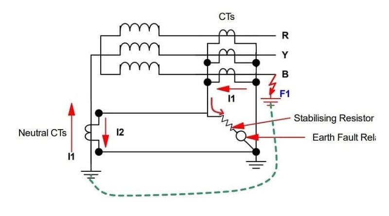
A power limited earth fault relay is the relay that can be described as part of a differential relay. The figure shows a representation of the earth fault relay with limited power. This definition is due to their connection. This relay is often used as a comparison relay for current flow in:
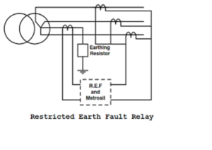 The earth fault relay is a special protective relay that detects and responds to earth faults when they occur in a specific area of an electrical system. Unlike traditional ground fault relays that detect faults based on the magnitude of the fault current, the REF relay compares currents at different points to identify potential weak points. The REF relay can quickly identify and isolate ground faults by monitoring the current imbalance between the protected area and the rest of the electrical system.
Working principle
An earth fault relay works on the principle of fault current detection by comparing the currents entering and leaving the protected zone. It uses a current transformer (CT) to measure currents. If the relay detects a significant difference between these currents, it indicates that an earth fault has occurred. The strength and phase angle difference between the currents help determine the location of the fault.
1) The neutral conductor of the instrument transformer is connected to the star point of the power transformer:
In a power transformer, the neutral conductor of the measuring transformer is generally connected to the star point of the transformer windings. This connection is essential for accurate measurements and protection purposes in electrical systems.
The measuring transformer, often in the form of current transformers (CTs) and voltage transformers (VTs), is responsible for reducing the high currents and voltages in the power system to values that can be measured safely and accurately by measurement relays. protection, meters and other monitoring devices.
The star point of a power transformer windings is normally grounded and represents the reference point for the system neutral. Connecting the measuring transformer neutral to the star point ensures that measuring transformer measurements accurately represent system currents and voltages.
2) Current flow within the instrument transformer (CT) connected to the neutral point of the transformer:
When a measuring transformer, particularly a current transformer (CT), is connected to the star point of a transformer, the current flow within the CT depends on the load and system conditions. Let's consider a typical scenario where the transformer is connected in a star configuration and the CT is connected to one of the phases.
Under normal operating conditions, load current flows through the primary winding of the power transformer. This load current also flows through the corresponding phase winding of the current transformer, which is connected in series with the primary winding. The primary winding of the current transformer has a significantly greater number of turns than the secondary winding. As a result, the current transformer reduces the current flowing through the primary winding to a lower magnitude suitable for measurement and protection purposes. The reduced winding is then available in the secondary winding of the current transformer for measurement and connection to monitoring devices or protective relays. As the current transformer is connected to the neutral point of the transformer, the current that flows through the neutral conductor of the power transformer also flows through the primary winding of the current transformer. This ensures that the current transformer accurately measures all current flowing into or out of the star point, including phase and neutral currents.
Error conditions
In the event of an error condition, such as: B. an earth fault or a short circuit, the fault current flows through the primary winding of the power transformer. The CT connected to the star point of the transformer also detects this fault current.
Internal errors
External faults
In the case of external faults (e.g. faults in the output power line), the differential current in this case is zero, the relay does not work and the circuit breakers cannot be tripped.
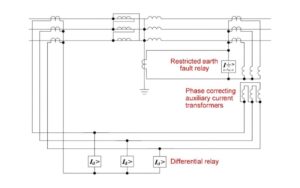
Principles and operation of differential relay
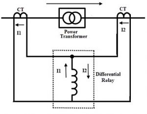
The operating principle of a differential relay is based on comparing currents or voltages entering and leaving a protected zone within an electrical system. The relay is designed to detect and respond to internal faults within the protected area, for example. B. Failures in transformers, generators, motors or buses.
Differential relays assume that currents or voltages entering and leaving the protected zone must be balanced under normal operating conditions. This balance results in a negligible voltage on the relay. However, if an internal fault occurs within the protected zone, the currents or voltages become unbalanced, creating a voltage difference across the relay.
Applications of earth fault relays with limited protection circuit
Earth fault relays with limited earth fault function are widely used in various electrical systems, especially in high voltage systems such as power transmission and distribution networks. They are typically used to protect power transformers, generators, motors and other critical equipment against ground faults. By selectively and quickly detecting faults, REF relays improve system reliability, minimize downtime and prevent damage to expensive equipment.
advantages and disadvantages
The advantages and disadvantages of earth fault relays are as follows:
Benefits
Improved sensitivity : REF (Restricted Earth Fault) relays can detect low-magnitude earth faults, improving fault detection sensitivity.
Selective error detection : REF relays allow selective detection and isolation of ground faults in specific zones, thus minimizing disturbances to the rest of the electrical system.
Disadvantages
Complexity : Installation and configuration of REF relays can be complex and requires careful configuration and coordination with other protective devices.
False Triggers : Incorrect configuration or external factors such as external leakage currents or transient events can cause the REF relay to falsely trip, resulting in unnecessary system shutdowns.
Conclusion
In summary, earth fault relays demonstrate the innovative power of combining safety and technology. Its silent surveillance and rapid response contribute to an ecosystem of reliability, ensuring electrical systems balance safety and operational excellence. As we move into an electrified future, these relays remain steadfast as essential instruments, orchestrating safety in the ever-evolving symphony of electrical engineering.