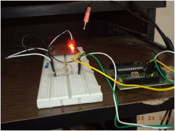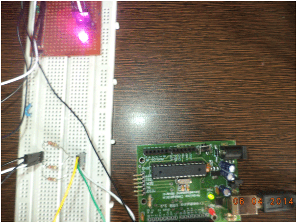
Fig. 1: Arduino-based RGB LED controller prototype
RGB-LED is widely used to generate lights of different colors in interior decoration, home appliances, automobiles, etc.
This article is about Arduino to get multiple colors with RGB LED and show the transition from one color to another.
The PWM output of an Arduino is an important tool for obtaining a variety of colors, be it Pink, Cyan, Magenta, Orange, Purple, etc.
An RGB LED is a four-terminal LED with a common pin (say cathode) and three other pins (anode) for Red, Green and Blue LEDs.

Fig. 2: Pin diagram and internal circuit of RGB LED
The first step, get an RGB LED and test it. To do this we need to connect the 5V power supply to the simple LED through resistors (330ohms).
Now that we have the colors RED, GREEN and BLUE individually, it's time to mix these three basic colors.
Get an Arduino (any basic board with at least 3 PWM outputs). I used an Atmega8.
Connect your Arduino, make proper connections as shown in the circuit diagram below.
Moving on, now it's time to control the LED. We will do this through the Arduino-IDE.
Go to Arduino-IDE, select the board type, in the 'Tools' menu. Select the COM port from the 'Serial port' menu.
After that, copy the sketch below and upload it.
Working:
Now, let's understand how this works. The ' analog write ' function of Arduino makes this possible.
Each Arduino digital output pin can provide a voltage of 0 or 5V, but the PWM pin has a complementary feature. It can provide various voltage values between 0V-5V.
Let's say we write,
analogWrite(red_led,50); //red_led refers to pin 9 (PWM pin)
This will give a voltage = (5/255)*50 V = 0.98 V at pin 9.
If we write:
analogWrite(led_azul,100); //blue_led refers to pin 10 (PWM pin)
This will give a voltage = (5/255) * 100V = 1.96V at pin 10
In this experiment, what we do is create a for loop to provide values between 0-255 on each LED pin with some delay (in milliseconds).
for(int i=0;i<=255;i+=3)
{
analogWrite(redPin,255-i); // write (255-i) to redPin
analogWrite(greenpin, i); // write I in greenPin
delay(100); //wait for 100uS
}

Figure 3: Image showing RGB LED being controlled by Arduino
Project source code
 ###


 int redPin = 10;
 int greenPin = 11;
 int bluePin = 9;
 void colorTransition ;
 void setup
 {
 pinMode(redPin, OUTPUT);
 pinMode(greenPin, OUTPUT);
 pinMode(bluePin, OUTPUT);
 }
 void loop
 {
 colourTransition;
 }
 void colorTransition
 {
 for(int i=0;i<=255;i+=3)
 {
 analogWrite(redPin,255-i);
 analogWrite(greenPin, i);
 delay(100);
 }
 for(int i=0;i<=255;i+=3)
 {
 analogWrite(greenPin,255-i);
 analogWrite(bluePin, i);
 delay(100);
 }
 for(int i=0;i<=255;i+=3)
 {
 analogWrite(bluePin,255-i);
 analogWrite(redPin, i);
 delay(100);
 }
 }

 ###
Circuit diagrams
| Arduino Based RGB LED Controller, Circuit Diagram |  |

