Random number generator with NRF24LE1
Random number sometimes plays an important role in our life. Think about a lottery ticket you bought. Now, what if a random number drawn from the draw matches your ticket number? We will be happy if that happens. Random number generators are also used to make games more intriguing and non-deterministic. Did you know that microcontrollers can also generate random numbers? Today we are going to discuss an interesting feature of NRF24LE1 which is Random Number Generator (RNG) .
The NRF24LE1 contains a thermal noise-based random number generator that produces a non-deterministic sequence. To make it more powerful and random, we can use a digital correction algorithm that removes any bias towards 0 or 1. This is also a built-in feature. RNG generates an 8-bit number that is stored in an 8-bit register. Therefore, the range of numbers will be 0 to 255.
Some characteristics of RNG are:
• Number generation rate of up to 10 kilobytes per second
• Non-repetitive sequence
• Works even when the NRF is in standby mode
• No initial input value is required for generation (autogeneration)
• Non-deterministic architecture based on thermal noise
RNG is controlled by two registers:
1. RNGCTL register (Random Number Generator Control) – It is an 8-bit register. The purpose of multiple bits is:
• Bit 7 – used to turn on RNG
• Bit 6 – used to activate the bias corrector
• Bit 5 – generation completed flag. 1: Data ready
• Bit 4:0 – not used
2. RNGDAT (Random Number Generator Data) register – It is an 8-bit register that classifies the generated number.

Fig. 1: Random Number Generator Prototype based on the NRF24LE1 Module
We will now cover the RNG process in simple steps.
• First we have to turn on the generator. To do this we have to write 1 in bit 7 of the RNGCTL.
• If we want to enable the polarization corrector we can write 1 in bit 6 of the RNGCTL.
• We can check if the number was generated by reading bit 5 RNGCTL. An RNGIRQ interrupt is also produced after a successful generation. It takes about 0.1 mS to generate a number when the bias corrector is disabled and four times as long when the bias corrector is enabled. Additionally, it takes about 0.25 ms for the first generation after the RNG is turned on.
• The generated one-byte data can be accessed through the RNGDAT register.
We can also use functions provided by the Nordic libraries:

Fig. 2: NRF24LE1 wireless module function listing table
Function Input Parameter Output Description
hal_rng_power_up 0/1 – To power RNG
0:OFF
1:ON
hal_rng_bias_corr_enable 0/1 – To use the bias corrector
0: Disable
1: Enable
hal_rng_read – 8-bit data to read the generated number
hal_rng_data_ready – 0/1 To check RNG status
0: Data not ready
1: Data ready

Fig. 3: Image of the random number generator based on the NRF24LE1 module
We write code so that users understand how it works. The generated 1-byte number was sent to Port0, where the LEDs are connected. As the number generated is random, these LEDs will flash randomly.
Project source code
###
//Program to#include"reg24le1.h" // I/O header file for NRF24LE1
#include"hal_delay.h" // header file containing delay functions
###
Circuit diagrams
| Circuit Diagram-NRF24LE1-Module-Random Number Generator | 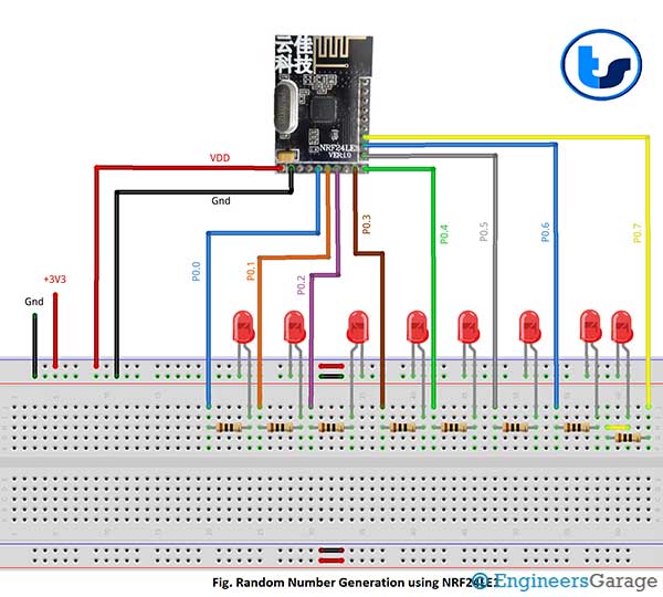 |
Project video