Voltage regulator is a device that provides fixed output voltage despite variable input voltage provided. It is a three terminal device. The voltage regulator basically comes in two different series: 78XX and 79XX. The 78XX series voltage regulators are designed for positive inputs, i.e., while the 79XX series is designed for negative inputs. In the market, a variety of voltage regulators are available with output of 6V, 9V, 12V, 15V, etc. The voltage regulator can also withstand overcurrent drawn due to short circuit or overheating. This will break the circuit before damage occurs. Care must be taken when assembling the regulator because reverse polarity can destroy the regulator.
The negative and positive voltage regulator pin configuration is shown in fig.
((wysiwyg_imageupload:8289:))
Fig. 1: Image of the 78XX and 79XX voltage regulator
Voltage regulator is a device that provides fixed output voltage despite variable input voltage provided. It is a three terminal device. The voltage regulator basically comes in two different series: 78XX and 79XX. Voltage regulator under 78XX series are designed for positive inputs i.e. while 79XX series is designed for negative inputs. In the market, a variety of voltage regulators are available with output of 6V, 9V, 12V, 15V, etc. The voltage regulator can also withstand overload of current drawn due to short circuit or overheating. This will break the circuit before damage occurs. Care must be taken when assembling the regulator because reverse polarity can destroy the regulator.
The negative and positive voltage regulator pin configuration is shown in Fig 1.
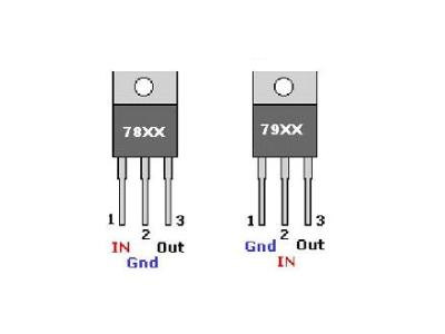
Fig. 1: Image of the 78XX and 79XX voltage regulator
As we know that the output of the regulator is fixed but with the help of voltage divider rule we can use 5V regulator to supply 12V. But the reverse is not possible as we cannot get 5V from the 12V regulator.
How do we calculate the resistor value for different voltages-
Suppose the value of the resistor connected between COM and the regulator output pin is 470ohm (R1). This means we have a current of 10.6mA (because V = 5V and V = IR) available between the pin, COM and the output. There would be some standby current of about 2.5 mA that will be available between the rotary switch and ground. Therefore, the total current available will be approx. 13.1mA. Now, let's say we want 5V to 12V from this circuit. For a minimum of 5V, we will get this directly from the regulator output. But if you want the maximum 12V, in addition to 5V, an additional 7V would require selecting the appropriate resistor.
Here R=?
V=7V
Eu=13.1mA
Therefore V =I*R
R = 543 ohms
So we have to connect a 543ohm resistor with 470ohm to get the desired output of 12V. But a resistor with this value may not be easily available, so we can use a resistor which has values close to it, viz. 560 ohms.
Now if you want to get different voltages between 5V and 12V then use different values of resistor like if you want to get 6V then-
V=6V
I = 10.6 mA
R=6V/10.6mA
R = 566 ohms
But we have already connected the 470ohm resistor R1 so, for 6V we have to use the resistor value =100ohm (566- 470ohm= 96 approximately 100ohm). Similarly, you can calculate different resistor values to obtain different voltages.
In this circuit we use different resistors to obtain different voltage values. You can also use a variable resistor to get the different voltage values with a single resistor.
You might like:
-
Designing a Switch Mode Power Supply (SMPS)
-
Adjustable power supply from +/- 1.25V to +/- 22V 1A
-
1.25V – 25V variable power supply using bridge rectifier
-
Variable power supply and charger with emergency light
-
Benchtop Uninterruptible DC Power Supply with Display
Circuit diagrams
| Circuit Diagram-Fixed Voltage Regulator Variable Power Supply |
Project Components
- Capacitor
- 1N4001 diode
- IC 7805 (Voltage regulator IC)
- relay switch
- Resistor
Circuit diagrams
| Fixed Voltage Regulator Variable Power Supply Circuit Diagram |  |
Project Components
- Capacitor
- 1N4001 diode
- IC 7805 (Voltage regulator IC)
- relay switch
- Resistor