This tutorial explains how to make your own power supply unit for all your electronics and embedded systems experiments. It also has a backup battery that will be used in the event of a power outage and display. For this project the reader must have knowledge of How to get started with AVR and LCD interface with AVR .
Required components
1. SLA 12V Battery11. Capacitors
12. Resistors 13. ATmega16/8 development board 14.LCD 16×2 15. Heat sinks 16. Cabinet
Characteristics:
– Inputs: 220-240 V, 50 Hz AC
– Outputs: 1 X 5V and 1 X 9V (available via banana connector)
1 X Adjustable voltage (available via screw terminal)
– Adjustable voltage range: 1.25-14.5 V in mains mode and 1.25-10.5 V in battery mode
– Modes: 1) Battery Mode and 2) Normal Mode (through the mains)
– Automatic switching and shutdown by microcontroller
– LCD with several indicators.
Block diagram

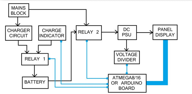
Fig. 1: Block diagram of benchtop uninterruptible DC power supply
Blue lines indicate signal lines and black lines indicate power lines. Let me explain what each block consists of and its function. Network block: This consists of the transformer, bridge rectifier circuit (4 diodes) and a capacitor. This block receives power from a wall outlet that provides 220-230 V AC. The step-down transformer reduces the amplitude of the sine wave, followed by the rectifier bridge that converts it into pulsating DC which, when passing through the capacitor, produces an unregulated DC power of 16-18V (voltage depends on the transformer)
Fig. 2: Circuit diagram of AC rectifier used as first stage of benchtop uninterruptible DC power supply
Charger circuit: This block mainly consists of an adjustable voltage regulator LM317 which together with other components works as a constant voltage and limited current charger for our battery. Once the battery is fully charged, the circuit automatically supplies low current to the battery and enters trickle charging mode.
Fig. 3: Circuit diagram of charger used as second stage of benchtop uninterruptible DC power supply
Load indicator: This is nothing more than two resistors arranged in the form of a voltage divider circuit. It reduces the battery voltage level so that the microcontroller can read it.
Relay 1: This is a relay module that switches between the charge indicator circuit and the charger circuit depending on the command from the microcontroller.
The +ve terminal of the battery is connected to the common pin. The charging circuit is connected to the Normally Open pin and the charging indicator circuit is connected to the Normally Closed pin. When the power supply is off, the relay disconnects the charger from the battery and connects it to the indicator so that the microcontroller can read the battery level and display it on the LCD. When the power is ON, the indicator circuit is disconnected and the charging circuit is connected to the battery.Relay 2: This relay module switches between mains power and battery power depending on the command from the microcontroller.
The +ve terminal of the battery is connected to the Normally OPEN pin while the +ve line of the main power supply block is connected to the Normally CLOSED pin. The common pin of the relay is connected to the DC PSU block. When mains power is unavailable, the controller automatically switches the relay to battery mode.
Fig. 4: Circuit diagram of charge indicator used as third stage of benchtop uninterruptible DC power supply
Note: The +12V to power the relay is supplied directly from the battery. This allows the relay to function purely based on microcontroller command rather than power availability.
DC Power Supply: This block consists of voltage regulators and several capacitors. +5V, +9V and adjustable voltage levels are provided by ICs 7805, 7809 and LM317 respectively.

Fig. 5: Circuit diagram of voltage regulators used as final stage of benchtop uninterruptible DC power supply
Panel display: This is the front and outer panel block which consists of main switch, LCD displaying voltage level, potentiometer knob for adjusting voltage, banana connectors and screw terminals.
This is how I want it to look:

Fig. 6: Image representing the benchtop uninterruptible DC power supply panel display
The icons on the LCD indicate the following:

Fig. 7: Image showing icons used in the display panel to show different battery status
Code Explanation
. Here, our development board performs the following tasks: – Calculate voltage levels at variable voltage terminal and battery level using ADC – Detecting the presence/absence of electrical grid – Switching sources and load indicator/charger controlling relays in appropriate events. – Displaying all above parameters on LCDSo our code algorithm looks like this: -Initializing I/O ports, ADC registers and LCD functions. – Enter infinite loop – Check power supply availability using ADC pin – if a power grid is available, display the corresponding icons on the screen – if the network is not available, switch to battery mode and turn on the charge indicator – Check battery level using ADC pin – If the battery level is >50%, <50%, <10%, display the corresponding icons on the LCD. – If the battery level is close to 0%, start the automatic shutdown sequence countdown.

Fig. 8: Image representing the character LCD pin diagram
Since in the last step the mains is unavailable anyway, the power supply to the microcontroller board, the LCD and the DC power supply is cut off and therefore the unit cannot be turned on again without supplying mains power.
If the mains becomes available during the shutdown process, the data on the LCD goes to waste and therefore we use a watchdog timer to reset the controller at the end. The +5V line is also connected to the microcontroller board and LCD.Circuit diagrams
| Circuit Diagram-Uninterruptible Power Supply-Top Bench-DC | 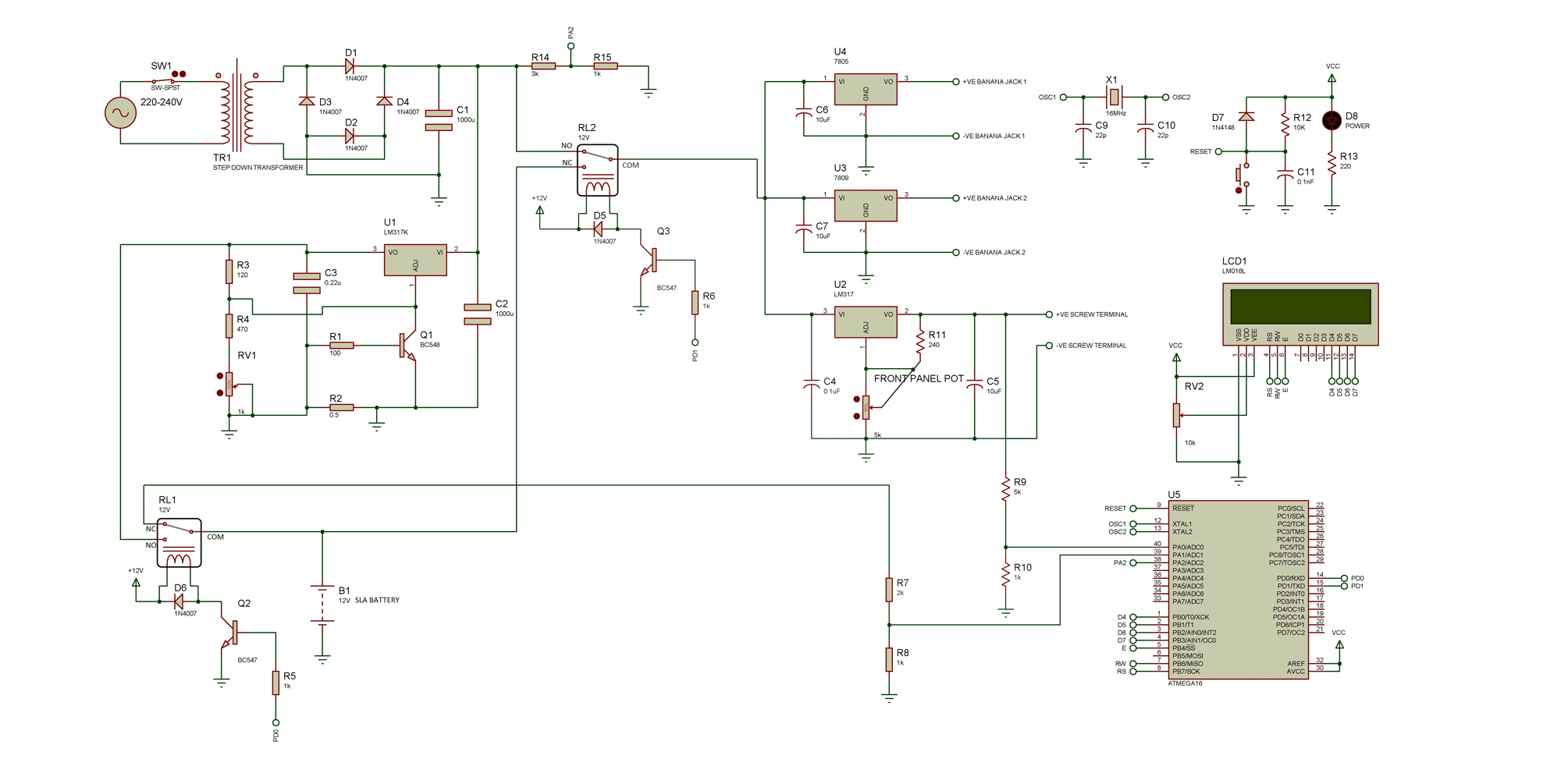 |