ESP8266 is a UART to WiFi module that provides an easy solution to connect any small microcontroller platform like Arduino to the Internet wirelessly. Since the ESP8266 is super cheap and super easy to work with, it has become one of the leading platforms for the Internet of Things. You can use AT commands to connect to WiFi networks and open TCP connections without running the TCP/IP stack. It also includes a 32-bit microcontroller that can be programmed to act as a standalone WiFi-connected embedded platform.
To start using the ESP8266 ESP-01, it is recommended to flash it and program it with the NodeMCU Firmware before building your project. So far, there are different variants of ESP-x modules available where x can be from 1 to 12. ESP8266 requires 3.3V device, it cannot tolerate 5V, so do not power it with 5 Volts. We have to make sure that the CH_PD pin is pulled high, the module will not give any response until you make this connection. This can be done by directly connecting CH_PD to VCC or you can also use the 3.3K resistance to go high. The nominal current of this module is 80mA in idle mode and 300mA during operation.
Entering firmware flash mode:
To put the ESP-01 into firmware flash mode, we have to make some changes to the state of the GPIOs. The board schematic in TOP orientation is shown below.
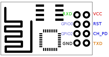
Fig. 1: Image showing the PCB layout of the ESP-01 ESP8266 module
Connections for Flash mode:
The normal connection details are as follows:
|
Wi-Fi module |
USB-TTL
|
|
Vcc |
3.3v |
|
Gnd |
Gnd |
|
Texas |
RX |
|
RX |
Texas |
|
CH_PD |
Connected to 3.3V to enable chip firmware initialization |
Don't forget to pull CH_PD HIGH, you will not receive response from the module if this is not done.
In addition to the connections above. To enter the firmware flash mode, we need to make an additional connection, the easiest way is to use a breadboard for this.
ESP-01 GPIO0 – Pull down connecting to GND
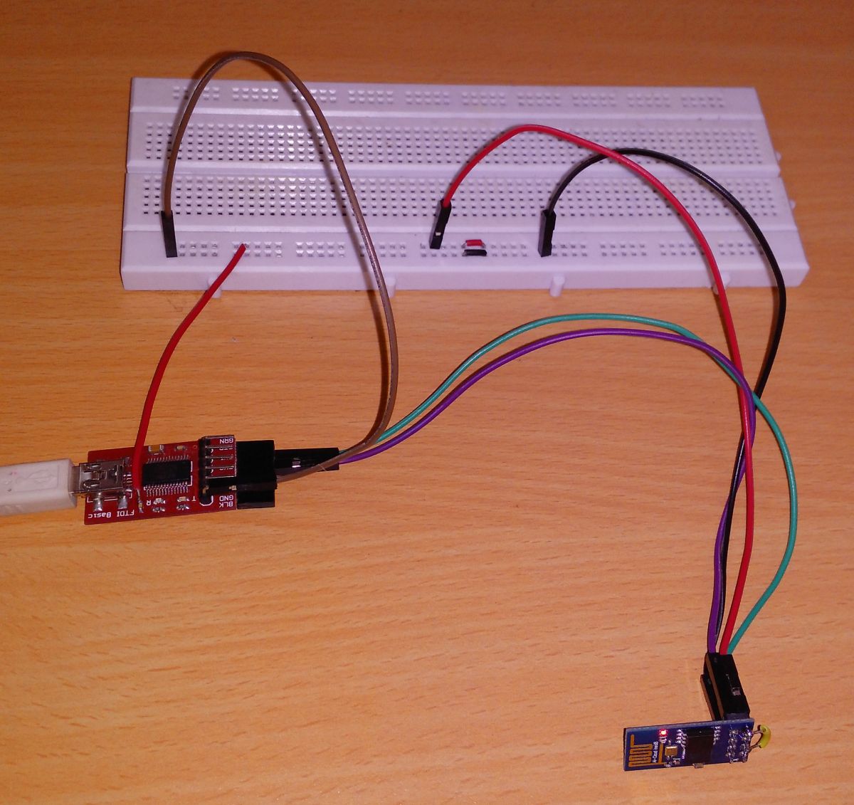
Fig. 2: Image showing circuit connections between ESP8266 module and FTDI converter
When you reboot the module, it should be in firmware flash mode!
Downloading the software:
Go to
There you click on the “Download Zip” button on the right of the screen.
A zip file with all files will be downloaded. Extract it and the file we are going to flash is nodemcu_512k_latest.bin which is located in the nodemcu-firmware-masterpre_build.9.4512k-flash directory.
However, it's even easier if you download the flasher itself because it contains the firmware!
Access and download the zip.
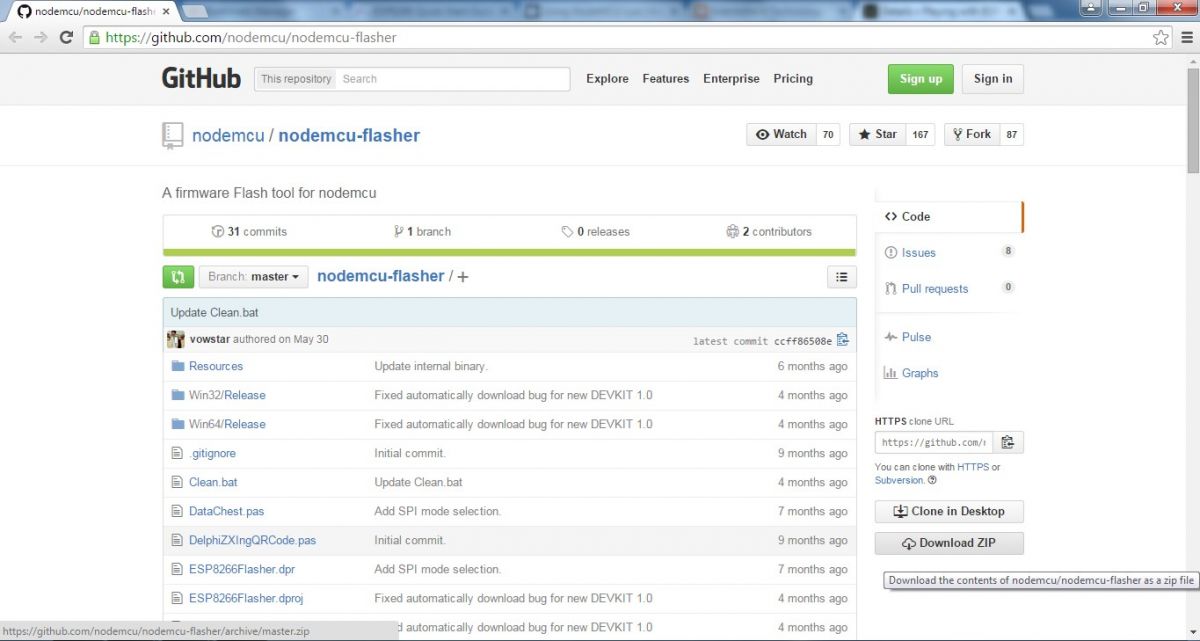
Figure 3: Screenshot of the Nodemcu-Flasher Github page
Choose the 32-bit or 64-bit version depending on your PC's operating system and open it. It should open like the image shown below.
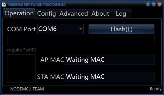
Fig. 4: NodeMCU firmware programmer screenshot
In most cases, this program will find the USB-TTL converter port automatically or else disconnect and reinsert the USB-TTL converter. Once connected, click the Flash button.
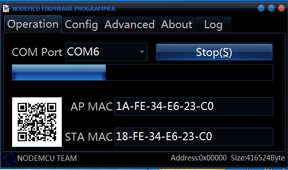
Fig. 5: Screenshot of NodeMCU firmware flashing
Wait until the progress ends and shows a green checkmark in the bottom left corner.
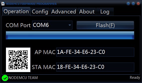
Fig. 6: Screenshot of NodeMCU firmware flashing in progress
Enter normal mode by disconnecting GPIO0 from GND.
You are now ready to program the ESP8266 for your own application.
The NodeMCU Lua firmware communicates with the PC via the serial link. You can use PuTTY or any other terminal program to write Lua programs or enter direct commands on the board. The default speed is 9600 baud, but it can be changed to any other baud rate after establishing communication.
Here we will discuss two software used to load LUA programs into the module among many of them.
LuaLoader
LuaLoader
LuaLoader.exe is a simple Windows application that does not require special installation. In addition to being a simple terminal program, it has integrated command buttons that facilitate interaction and experimentation with the ESP8266 board.
Download: LuaLoader.zip
From the Settings menu, select COM Port Settings and choose the appropriate COM port for your USB to Serial Adapter.
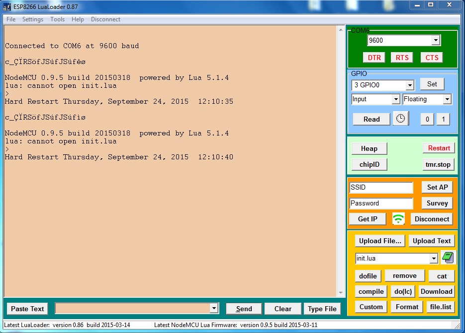
Figure 7: LuaLoader screenshot
Clicking on the LuaLoader buttons sends commands to the board that are already pre-determined. Turn on your board and observe the initial message. You should see the NodeMCU version information after displaying some funny characters which are firmware reset parameters sent at 74880 baud.
NodeMCU 0.9.5 build 20150107 powered by Lua 5.1.4
After each reboot, NodeMCU will attempt to run a file called init.lua in flash memory. Since this is the first boot, it will report an error and show the prompt . This shows that the module is now ready to interact.
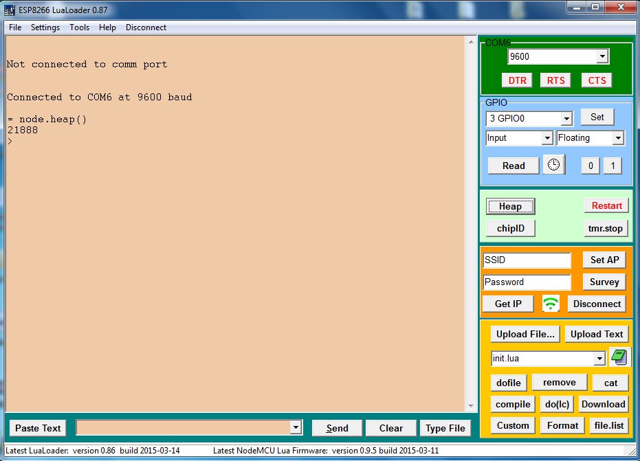
Figure 8: Screenshot of LuaLoader running init.lua
For information about the amount of available RAM, click the Stack button. LuaLoader will type the command = node.heap and the ESP8266 will respond with 21888 or some other value, followed by the > prompt again.
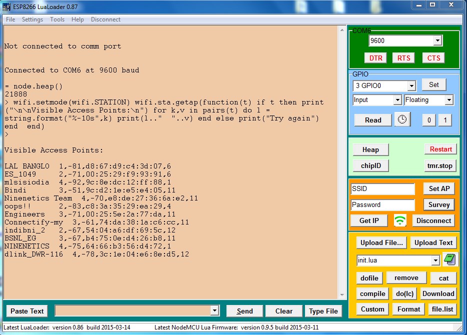
Fig. 9: Screenshot of obtaining information about the amount of RAM available in LUALoader
Click the Poll button to list the available access points visible to the ESP8266. The SSID, authentication mode, signal strength, MAC address and channel are shown.
Connecting to an access point:
Enter the SSID and password of your nearest access point into the appropriate text box in LuaLoader. Click Set AP . LuaLoader will send the commands to set WiFi mode and connect to it.
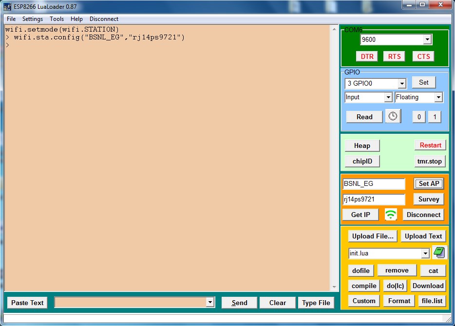
Fig. 10: Screenshot of connecting to an access point in LuaLoader
click on the WiFi button to check the connection status. Click Get IP to confirm whether the ESP8266 is connected to your access point.

Figure 11: Screenshot obtaining IP in LuaLoader to confirm connection with ESP8266 module
All commands entered by clicking LuaLoader buttons can also be entered manually or saved to a file to be executed automatically.
Here is the video of NodeMCU firmware flashing on Esp8266 using Windows