Password-based locking for any access control system is very common nowadays. If there is a password lock for any gate/door, the gate or door will only open when the correct password is entered. Mostly in such system numeric keypad is provided to enter password. The sequential code lock differs here from the normal password lock system. It does not have a full numeric keypad with 10 to 12 keys. Instead, it only has 2 to 3 switches. The user must enter the correct sequence of numeric digits, as well as the sequential locks available in the folders. When the numeric digits are arranged in the correct sequence, it is unlocked.
In this project, the user must first set the correct sequence of digits by scrolling them from 0 to 9 by pressing just 1 button, similar to scrolling and digit setting in the folder lock. User must define all digits one by one to complete the sequential code. The project is built using AT89C52 microcontroller. It uses LCD to display various messages. The stepper motor is used to illustrate the opening and closing of the gate.
Circuit Description

Fig. 1: Circuit diagram of 8051 microcontroller based sequential code locking system
Port P1 is configured as input and 3 buttons are connected to pins P1.0 to P1.2, so when the button is pressed the pin gets 0 as input
· Port P0 is an output port and drives LCD data pins D0 – D7. Another two P2 port pins P2.7 and P2.6 are connected to the LCD control pins Rs and E. The third control pin RW is permanently connected to ground to make the LCD always write-enable
· A 1K potentiometer is connected to the Vee brightness control pin of the LCD to vary its brightness
· Port P3, pins P3.4 – P3.7, drives the stepper motor through the ULN2003A motor driver chip. The motor opens or closes the gate
· A 12 MHz crystal is connected between the XTAL pins along with two 33 PF bias capacitors. It provides clock signal to the microcontroller
Circuit Operation:
· When the system is turned on, the gate is closed and the message is displayed on the LCD as “To open the gate, enter the code”
· To enter the code, the user must press the number key. He has to keep pressing the number key again to scroll all the digits from 1 to 0. Just like pressing the key once will display digit 1, pressing the key twice will display digit 2, similarly 3, 4, 5, ….. up to 0 and again starts from 1
· Once you reach the desired digit, to define the digit you must press the second button to define the digit as the 1st digit of the code. After setting the first digit, the cursor changes to the position of the second digit
· Again user has to scroll through the digits starting from 1 and reach the desired digit using 1 st button. Set the second digit of the code by pressing 2 and button
· Likewise, the user must define a 4-digit code. After the 4-digit code is set, the user will press the Enter button
· When the Enter button is pressed, the microcontroller will compare the entered code with the programmed code
· If they match, the motor rotates clockwise to open the gate and the message is displayed on the LCD as “gate open”. After 5 seconds again the motor turns counterclockwise to close the gate and the LCD displays “gate close” and then again the standard message “To open gate Enter code” is displayed
· But if the code does not match, the engine stops and the warning message is displayed as “wrong code”. Furthermore, if the wrong code is entered 3 times, the system goes into an infinite loop (this means it crashes). It can exit the loop only when the reset button is pressed to restart the system again.
Project source code
###
#include#include
#define ON 0
#define OFF 1
sbit rs = P2 ^ 7;
sbit en = P2^6;
sbit unlock_led = P2^0;
sbit lock_led = P2^1;
unsigned int number_count=0,code_num(4),code_digit=0,set_count=0,gate_flag=0;
unsigned int code_lock_num = 1122, attempt = 0, reset_flag = 0;
void dly
{
int y,z;
for(z=0;z<100;z++)
for(y=0;y<1000;y++);
}
empty motor_delay
{
intp;
for(p=0;p<2000;p++);
}
empty wait_for_5_sec
{
int r,s;
for(r=0;r<100;r++)
for(s=0;s<10000;s++);
}
empty lcd_delay
{
internal;
for(y=0;y<2000;y++);
}
void writecmd (unsigned character a)
{
lcd_delay;
rs = 0;
P0 = one;
en = 1;
en = 0;
}
void writedat (unsigned character b)
{
lcd_delay;
rs = 1;
P0=b;
en = 1;
en = 0;
}
void writestr(unsigned character *s)
{
unsigned character l,i;
i = strlen(s);
for (l=0;l
{
writedate(*s);
s++;
}
}
empty lcd_init
{
writecmd(0x3C);
writecmd(0x0E);
writecmd(0x01);
writestr("To open the gate");
writecmd(0xC0);
writestr("Enter code:");
}
null initialization
{
P1=0xFF;
P0=0x00;
P2 = 0x00;
P3 = 0x00;
}
empty open_gate
{
unsigned int i;
writecmd(0x01);
writestr("Gate open");
for(i=0;i<128;i++)
{
P3 = 0x8F;
motor_delay;
P3 = 0x4F;
motor_delay;
P3 = 0x2F;
motor_delay;
P3 = 0x1F;
motor_delay;
}
wait_for_5_sec ;
writecmd(0x01);
writestr("Gate closed");
for(i=0;i<128;i++)
{
P3 = 0x1F;
motor_delay;
P3 = 0x2F;
motor_delay;
P3 = 0x4F;
motor_delay;
P3 = 0x8F;
motor_delay;
}
}
empty number
{
if(set_count==0) writecmd(0xCB);
else if (set_count==1) writecmd(0xCC);
else if(set_count==2) writecmd(0xCD);
else if(set_count==3) writecmd(0xCE);
count_number++;
if(number_count==1) {writedat(0x31);}
else if(number_count==2) {writedat(0x32);}
else if(number_count==3) {writedat(0x33);}
else if(number_count==4) {writedat(0x34);}
else if(number_count==5) {writedat(0x35);}
else if(number_count==6) {writedat(0x36);}
else if(number_count==7) {writedat(0x37);}
else if(number_count==8) {writedat(0x38);}
else if(number_count==9) {writedat(0x39);}
else if(number_count==10){writedat(0x30);number_count=0;}
}
empty set_number
{
set_count++;
code_num(digit_code)=count_number;
number_count=0;
digit_code++;
}
void enter_number
{
int unsigned tmp;
tmp= code_num(0)*1000+code_num(1)*100+code_num(2)*10+code_num(3);
if(tmp == code_lock_num)
{
unlock_led = ON;
lock_led = OFF;
open gate;
gate_flag=1;
set_count=0;
digit_code=0;
attempt=0;
}
other
{
writecmd(0x01);
writestr("wrong code");
attempt++;
if(attempt==3)
{
writecmd(0x01);
writestr("attempts closed");
writecmd(0xC0);
writestr("System locked");
reset_flag=1;
}
other
{
writecmd(0xC0);
writestr("try again");
gate_flag=1;
set_count=0;
digit_code=0;
}
}
}
main void
{
initialize;
again: lcd_init ;
gate_flag=0;
unlock_led = OFF;
lock_led = ON;
return: P1=0xFF;
while(P1==0xFF);
switch (P1)
{
case 0xFE:
number;
dly ;
to break;
case 0xFD:
set_number;
dly ;
to break;
case 0xFB:
insert numbers;
dly ;
to break;
}
if(reset_flag==1) goes to infinity;
else if(gate_flag==0) go back;
otherwise go to again;
infinity:while(1);
}
###
Circuit diagrams
| Circuit Diagram-8051-Microcontroller Based Sequential Code Lock System | 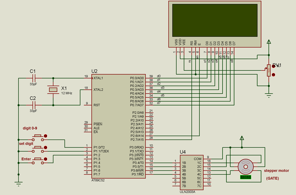 |