Stator winding short circuit protection
Back to back or short winding in the same stator phase winding can never be captured by percentage Differential protection relay which is also called modified Merz price differential relay This is because the current produced by these types of faults flows in a circuit local between the affected windings and does not produce a difference between the currents entering and leaving the winding at the two ends where the current transformers are placed.
If this stator only has one coil per slot, short winding cannot occur. If there are multiple coils per slot, turn-to-turn failure is likely to happen.
Instead of a series differential relay Cross differential relay is used to Fault between the stator windings.
In multi-winding stators, such as those used in hydroelectric generators, each phase winding is divided into two halves because they must transmit very high currents.

Parallel Winding Generator:
The schematic diagram of a pre-charged transverse differential protection for shorted stator winding is shown in the figure above.
This type of protection requires special winding precautions. To identify the fault occurring between turns, each winding (phase) is divided into two parts as shown in the figure. Under normal conditions, the current through the two windings is equal. Therefore, the currents through the secondary winding of the two CTs are equal and no current flows through the operating coil of the relay, hence the relay does not work. If a fault occurs between the turns, the current through the two CTs is not equal and therefore the difference in current flows through the relay operating coil. The relay energizes and closes the trip circuit to isolate the faulty sections.
Generator with one winding per phase vector and inaccessible parallel winding

This type of protection uses zero sequence voltage components caused by the reduction of electromotive force in the faulty phase. When the error occurs, zero system voltage appears above Tertiary winding of Voltage Converter which is connected to the operating coil of the three-element directional relay and therefore operates the relay.
Limited protection against earth faults through differential system
If the neutral wire of the generator is firmly grounded it is possible to protect complete windings against phase-to-ground error .
As the neutral is grounded through a resistor to limit the ground fault current, with this type of grounding it is not possible to protect the entire winding against ground fault and the percentage of winding protected depends on the value of the grounding resistance of the neutral and of the context relay. The configuration must be done so that the protection is not for Earth Faults on the EHV page. Ground faults are unlikely to occur near the neutral where the relative voltage to ground is lowest. It is common practice to protect about 80 to 85% of the generator winding against ground faults. The remaining 20 to 15% of the neutral side winding remains unprotected by the differential relay. Therefore, a separate Earth Fault Protection is intended to protect the entire winding against earth faults.

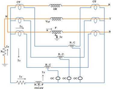
If there is an earth fault in the generator winding (GW), the residual current is I F flows through part of the winding and the neutral-to-earth circuit. The corresponding IS secondary current flows through the operating coil (OC) and the Limited Earth Fault (REF) Differential Protection Relay coil as shown in the figure above.

If the ground fault I F occurs at point F of the generator winding, V af is available to drive the ground fault current I F through the neutral-to-ground connection. If point 'F' is closer to 'a', i.e. closer to neutral, the power voltage is V af is relatively low. Therefore, the earth fault current is I F will be small. It is not practical to keep the relay setting too sensitive to detect small magnitude ground fault currents. Therefore, the practice is to protect about 85% of the generator winding against phase-to-ground faults and leave the 15% portion unprotected by differential protection against ground faults.
Resistor R limits the ground fault current as shown in the figure above. If R is too small, solid ground will not be used. Solid grounding is limited to 3.3 KV. With low-resistance grounding, the resistance R is so high that full current flows through the neutral to ensure full voltage between the conductor and neutral. For a 60 MW generator, the resistance is so high that earth is about 200 A. For high resistance earthing, the maximum earth fault current is on the order of 10A, which is typically the case for distribution transformers and generator transformer units. If the resistance of the neutral conductor is greater, the earth fault current will be reduced. Therefore, a smaller percentage of the winding is protected by limited ground fault protection.

