

In electrical engineering, grounding techniques are the backbone of safe and efficient power systems. Proper grounding plays a critical role in mitigating electrical hazards and ensuring reliable operation of many of the technologies we depend on every day – from personal computers and cell phones to multimedia devices such as audio and video players. This fundamental understanding ensures that our devices, including portable media players and MP3 players, function optimally and safely. Likewise, backfilling practices impact the stability and performance of online information systems and software infrastructure in Internet and web technology. Whether it's a home equipped with smart technology or an industrial complex powered by complex networks, implementing effective grounding practices is critical for engineers, electricians and technicians. As we explore electrical grounding techniques, we delve deeper into the fundamental principles, innovative approaches, and best practices that enable professionals to create robust, resilient electrical systems. Embark on this insightful journey to discover the transformative impact of grounding techniques and unlock the secrets to safer, more optimized electrical infrastructure.
Electrical grounding techniques
Electrical Grounding Techniques are as follows:
- Solid grounding
-
Resistive grounding
-
reactor grounding
-
Arc suppression coil or Peterson coil or resonant ground
-
Grounding of voltage transformers
-
Zigzag Transformer Grounding
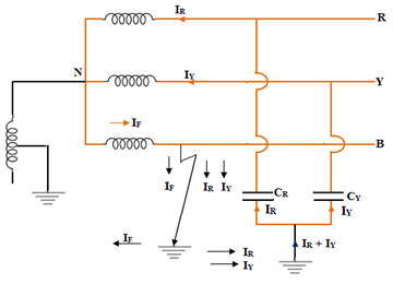
Solid grounding
-
If an earth fault occurs between earth and any phase, the voltage to earth of the faulty phase becomes zero. However, the healthy degree remains at normal phase values. Therefore, arresters with low voltage ratings can be used, saving costs.
-
The flow of the strong fault current I F completely cancels the effect of the capacitive IC on the marking, so that no ground arcs or overvoltages occur.
-
Due to the high fault current, a protective relay circuit is possible.
-
An increase in ground fault current causes disturbances in neighboring communication lines.
-
High fault currents can cause damage to the Circuit Breaker Contacts.
-
Solid grounding is limited only to systems where the normal circuit impedance is sufficient to prevent very high fault currents.
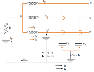
Resistive grounding
-
Allows the use of discriminatory protective equipment .
-
Minimizes the risk of ground faults
-
Limiting fault current reduces interference to neighboring communication lines
-
Typically used for short lengths of wire with low current
-
Comparatively more expensive than solid grounding
-
Improved stability
reactor grounding
Where X Ó = zero reactance of the system
X 1 = positive reactance of the systemP
For solid grounding (X Ó X 1 ) > 3
If a neutral wire is solidly grounded and (X Ó X 1 ) > 3, the system is considered reactance grounded. Reactance grounding is between effective grounding and resonant grounding. The reactance value keeps the fault current within limits.
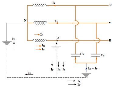
This method is used to ground synchronous motors, capacitor banks and circuits with large load currents.Arc suppression coil (Peterson coil)
The shunt is used to select the reactance of the Peterson coil depending on the length of the transmission line and therefore the capacitance to be neutralized. The reactor can be tuned with the ability of the healthy phases to produce resonance in the event of a line-to-ground (LG) fault.
It is mainly used for Preventing ground faults that cause surges in the system with ungrounded (isolated) neutral.
The Peterson coil ensures that arc faults are self-extinguishing. If there is a persistent ground fault on one of the lines, it reduces the fault current to a very low value so that the healthy phases can be kept in operation even with a grounded line.
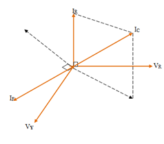
I C = 3I = {3V phone / (I / ωC) } = 3V phone ωC
Where IC is the charging current.
IL = V phone /ωL
To satisfactorily neutralize electric arcs, the fault current flowing through the Peterson coil must be equal to I. C
I M = IC, i.e. V phone / ωL = 3Vph ωC
L = 1/3ω 2 C
C = ground/phase line capacity
f = frequency
For neutral grounding of transformer LV circuit
Z N = V2 / (hxKVAx1000) ohms
where KVA = power of a transformer
Z N = impedance in the neutral conductor
L = line voltage on low voltage side
h = neutral conductor semiconductor current in relation to the line current at full load.
Earth arc
Grounding transformer
Grounding Methods for Voltage Transformers
Voltage transformers are crucial in electrical power systems as they ensure accurate measurement and control of voltage levels. To ensure optimal performance and safety, effective grounding techniques are essential. By implementing robust grounding practices, voltage transformers can operate reliably, minimizing the risk of electrical failures and improving overall system performance.
A crucial aspect of grounding voltage transformers is establishing a solid ground connection. The transformer ground connection is firmly connected to a low impedance ground electrode, such as a ground rod or metal ground grid. The main purpose of this connection is to provide a safe path for residual currents and potential surges and dissipate them without causing damage to the ground.
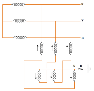
Zigzag transformer grounding
Zigzag transformers are a special type of grounding transformer often used in power distribution systems to provide a neutral connection and balance unbalanced voltages and currents. The unique design of zigzag transformers allows for effective grounding techniques that improve system performance and safety.
The main function of a zigzag transformer is to provide a grounding path for unbalanced currents. This is achieved by interconnecting windings arranged in a zigzag pattern. This configuration creates multiple grounding points so that the transformer can divert unbalanced currents and avoid possible interference and damage to equipment.
By connecting the transformer's ground winding in a zigzag pattern to the system's neutral conductor, residual currents and harmonic components are effectively balanced, reducing the risk of voltage distortion and creating a more stable electrical environment. This balanced grounding approach helps maintain equipment integrity and prevent the occurrence of excessive voltage levels that could pose a risk to sensitive electronic equipment and protective systems.
Zigzag transformers also play a crucial role in limiting the effects of ground faults. In the event of a ground fault, the zigzag transformer provides a low-resistance path for fault currents, allowing rapid fault detection and isolation. By quickly dissipating residual currents, the transformer protects equipment from permanent damage and helps maintain the overall reliability of the power system.
Conclusion
Grounding techniques are essential for my technology company because they ensure safe and efficient power systems for users to access tools and services. These techniques protect data and help staff maintain high standards. The number of employees plays a crucial role in the effective implementation of grounding methods.
Content creators on YouTube, Google, and Instagram benefit from basic practices to optimize information sharing. For companies like GE Healthcare in the US, grounding techniques improve efficiency and address service challenges. The customer experience is enhanced and desktop software and other technical support is provided.
In short, fundamental techniques are essential to Mytech's mission of providing reliable tools and services to its customers. They enable the company to overcome challenges and provide valuable information in a connected world.


