Differential relays play a critical role in the safety of electrical systems by detecting and responding to anomalies in current flow. They often have a delay mechanism to prevent false alarms. Understanding the principle and operation of these relays, manufactured by several leading companies, is crucial for engineers and technicians working on power systems. In this article, we will explore the intricacies of differential relays, examine their underlying principles, and how they work. We also investigate its applications in voltage and line protection as well as overcurrent and undervoltage detection. We also look at the importance of impedance relays and grounding protection in ensuring the overall safety and stability of electrical systems. Engineers can effectively use differential relays to mitigate risks and prevent potential damage or failure in power systems by understanding the interaction between phase currents and voltages.
What are differential relays?
How to measure and protect current transformers
Differential relay working principle
- Understand the basic principle of current balancing in differential relays
- Exploring the concept of power transformers and their role in relay operation
- Analysis of the most important principles of Kirchhoff's current law and the superposition theorem
How to Find Transformer Rating in KVA
To determine the kilovolt-ampere (KVA) rating of a transformer, you must consider several factors such as input voltage, output voltage, and load characteristics. The rated power of a transformer refers to its load capacity, expressed in KVA.
The primary rating of a transformer is generally based on the input voltage and maximum current that the winding insulation can safely handle. The nominal voltage represents the magnitude of the voltage applied to the primary winding of the transformer. The rated current indicates the maximum current that can flow through the primary winding without exceeding its thermal and electrical limits. These ratings are usually provided by the manufacturer.
The KVA rating of a transformer is calculated using the formula: KVA = (Voltage × Current) / 1000. The voltage and current values in this formula must be the root mean square (RMS) values of the respective quantities.
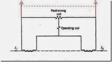
External fault condition in the differential relay

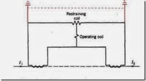
Internal fault condition in differential relay

Differential Relay Wiring Diagrams
Differential relay schemes include a series of techniques designed to ensure accurate and reliable operation when detecting faults in electrical systems. A commonly used scheme is the differential percentage scheme, which compares the currents entering and leaving a protected zone and triggers an alarm or trip signal when an imbalance is detected. Another approach is the harmonically restricted differential scheme, which includes filters to block harmonics and reduce false triggers caused by harmonic currents. Biased differential schemes introduce a bias current to increase sensitivity and improve stability. Each scheme has advantages and limitations, and selection of the most appropriate scheme depends on factors such as system configuration, failure modes, and desired sensitivity. Proper selection and implementation of the appropriate differential relay scheme plays a crucial role in achieving effective fault detection and ensuring the reliability of electrical systems.
Challenges and solutions
The operation and principle of differential relays present certain challenges that ensure accurate and reliable performance. A common challenge is saturation of power transformers (CTs). During fault conditions or high load currents, the CTs can become saturated, resulting in inaccurate current measurements and potential false relay tripping. Advanced CT designs and saturation detection algorithms improve relay sensitivity and prevent false triggering. Another challenge is the presence of inrush currents during transformer excitation or motor starting, which can simulate fault currents and cause false trips. Various techniques such as B. Harmonic blocking and retention algorithms distinguish between true fault currents and inrush currents, ensuring proper relay operation. Furthermore, it is challenging to coordinate differential relays with other protection devices to prevent malfunctions and optimize system performance. Appropriate relay configurations, coordination studies, and communication-enabled relays help overcome these challenges and ensure accurate and reliable operation of differential relays to protect electrical systems.
Advances in differential relay technology
Advances in differential relay technology have ushered in a new era of improved performance, intelligence and communications capabilities. The widespread adoption of digital relays has revolutionized the field, offering greater accuracy, faster response times and expanded functionality. These relays utilize digital signal processing techniques and advanced algorithms to achieve accurate fault detection and discrimination. Additionally, adaptive algorithms have emerged that allow the relay to adjust its settings based on system conditions, improving sensitivity and reducing false trips. Communication-enabled relays have also become more important, enabling seamless integration into smart substation automation systems. These relays can exchange data with other protection devices, allowing for better coordination, system monitoring and fault analysis.
Furthermore, new technologies such as artificial intelligence and machine learning offer great potential for optimizing differential protection. These technologies can enable relays to learn from historical data, adapt to changing system conditions, and more accurately identify complex fault patterns. As differential relay technology advances, power system protection can benefit from greater intelligence, reliability and adaptability, resulting in more robust and efficient electrical networks.
Conclusion
Frequently Asked Questions (FAQ)
What is the principle of a differential relay?
The purpose of a differential relay is to compare the input and output quantities or currents of a protected zone, in order to detect faults or anomalies.
What are the advantages of a differential relay?
Differential relays allow quick and sensitive detection of internal faults, mainly in generators, transformers and motors. They are less affected by external conditions and can detect errors in heavily loaded systems.
How does a differential relay work?
A differential relay compares the current entering and leaving a zone. When an imbalance or fault occurs, the differential current exceeding the set value causes the relay to activate and initiate protective measures.
What is a percentage differential relay?
A percentage differential relay is activated when the measured current difference exceeds a certain percentage of the compared average currents, providing better sensitivity and selectivity in fault detection.
What are pilot wires in a differential relay system?
Pilot lines are dedicated communication lines that transmit electrical signals between elements of the relay system. They ensure accurate and synchronized measurements for coordinated protection and reliable fault detection.