INTRODUCTION – Field emission display is all about the sharp features of a display at a very low cost.
Field emission display (FED) is a type of flat panel display that is thinner, brighter, lower power consumption and cheaper than liquid crystal display (LCD). FED, also called Nano Emissive Display (NED), consists of millions of accelerated electrons charged by much less voltage, compared to the high voltage for large-screen HD LCDs. These electron emitters are controlled by cold cathodes to generate colored light and are emitted towards the phosphor plate and this phenomenon creates moving images. The FED has a wide viewing angle and offers the brightest colors among the latest plasma and other displays.

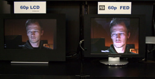
Figure 1: An image showing quality comparison between LCD 60p and FED 60p
In place of CRTS, carbon nanotubes (CNT) can also be used to direct electron beams onto phosphor-coated displays, which will further increase resolution. The FED is very thin, less than an inch, so we can easily hang them on the walls as a portrait and is capable of offering 20,000 to one contrast and can flash 240 images per second, double the fastest HDTVs on the market. The FED has another type of surface conduction electron emitting display (SED), which is based on surface electron conduction technology. FED can be used for television, desktop, laptop, etc. and has applications in medical imaging, defense and many other fields.
FIELD EMISSION PROCESS – Emission occurs from one medium to another and this medium can be solid, liquid, air, vacuum or any dielectric. Field emission is also called directional quantum mechanical tunneling “cold emission”, which occurs due to the electrostatic field. Thermal emission, which is the basis of CRTs, requires high operating temperature, consumes a lot of energy and is not energy efficient as it loses due to the disturbance of kinetic energy. On the contrary, field emission extracts electrons through a large electric field without the need for high temperature. This resulting electron source has reduced emittance and no heat problem, which is why field emitters are a “cold cathode” electron source.
Field emission based electron sources have many applications as they provide smaller spots, but the most undesirable and unappreciable aspect to engineers is that they introduce electrical discharge and vacuum breaking.
Field emission guns provide higher current densities than thermionic guns.
Figure 2: Diagram showing the metrology of high current density electronic field emitters
Application
FIELD EMISSION APPLICATION –
-
Field Emission Display (FED)
-
Field Emission Electric Propulsion Thruster (FEEP Thruster)
-
Field emission scanning electron microscopy (FESEM)
-
Gun or field emission sources (EMG) – Electrons are emitted by tunneling through the potential barrier at the tip of the surface due to the formation of a very high potential field gradient.
-
Atomically Sharp Emitters
-
X-ray and microwave generation
-
Neutralization of space vehicles
FIELD EMISSION DISPLAY – Flat panel technology has two leading but unnatural technologies: Field Emission Display (FED) and Thin Film Transistor Light Emitting Polymer (TFT LEP). Both technologies are emissive and quite transmissive, just like TFT LCD, so they both offer very wide viewing angles and high contrast ratios in well-lit environments.
The idea behind FED is to give each pixel a separate electron emitter, compared to just a single one on the CRT, resulting in an ultra-high definition image with unparalleled clarity and no blur. Carbon nanotubes can also be used as an electron-emitting source and the sharp tip of the emitter allows electrons to be stripped from the nanotubes at surprisingly low voltages. FED employs arrays of small pointed silicon or molybdenum cones that are deposited on a substrate within an etched hole. The result is a triode structure with a diameter between a few and less than a micron, of which there are thousands per individual pixel. The traditional FED structure used many micro tips, which were blue, red or green and together formed a pixel. Because FEDs display colors sequentially, FED advantages include the fact that they only produce light when the pixels are “on,” and as a result, power consumption depends on the contents of the screen. The electrons leave sharp ends at relatively low withdrawal voltages at the gate. Field emission from a flat cathode plane reduces the need for fine lithographic features and relaxes the tolerances required of the triode structure.

Figure 3: Diagram explaining the principle of displaying field emissions in the FED
Photolithography is used to make a series of rows of switching gates perpendicular to the cathode lines, forming an addressable grid, and a small patch of emitters is deposited at the intersection point of these rows and columns. A metal grille is placed on top of the switching ports.
The best comparison between CRT and FED can be made on field strength, considering that a large CRT uses 35-45 kV across a 2-foot anode-cathode gap, while a FED uses hundreds of Volts up to 10 kV across a 2-foot gap. of millimeters.
'PixTech' is a display company that manufactures FEDs and its first target areas were avionics, medical devices and motor vehicles. These markets were interested in smaller screens, in the 4- to 8.5-inch diagonal range, and very bright screens that could be read at wider angles than those available with LCDs. Also in January 1997, PixTech received the “Display of the Year” award from Information Display magazine. The technology has yet to see any mass market. Some partners of 'PixTech' are Raytheon, Texas Instruments, Futaba and Motorola and show their interests in FEDs.
POWERED NANO TUBE CATHODE – The FED can use recent technology of carbon nanotubes as an emission source which are made from hollow cylinders made entirely of elemental carbon, a nanotube is a thousand times smaller than a strand of human hair. They can also be thought of as a sheet of graphite (a hexagonal carbon lattice) rolled into a cylinder. The metal tips of the FEDs are replaced by CNT-based emitters. The electric field is generated by a gate electrode contained in each sub pixel and the anode is placed between the screen glass and the phosphor layer, the emitted electrons are swept through the vacuum towards their respective phosphors, i.e. red , green or blue (RGB), where light is emitted when the phosphors are struck.
CNT FED typically has an operating range of 50 to 100 volts, but the drive current is much lower.
The Samsung SDI group demonstrated a 38-inch CNT-FED at the 16th International Vacuum Microelectronics Conference. The growth of CNT directly on the cathode substrate is in the pipeline with companies such as Motorola and LETI, while Samsung and ANI are working to enable CNT printing because the printing approach is more conducive to manufacturing large areas, offering uniform emission. in high volume, as opposed to the high-temperature CVD (cathodic vapor deposition) approach required for direct CNT growth.
Printable field-emitting (PEE) materials are produced as ink and can be deposited using, for example, screen printing technology, making them instantly attractive for use on wide-area substrates. The E-band structure of the joint matrix and particle means that each particle in the compound acts as an individual field-emitting site. Unlike microtips, PFE cold cathode materials are extremely robust and relatively insensitive to low vacuum. PEE will also allow operation with large triode structures and the feature size is also compatible with screen printing technology.

Figure 4: Diagram showing the structure of the CNT-FED
Benefits
Some advantages of CNT FEDs are:
-
High contrast and luminance
-
High chemical stability
-
Great thermal conductivity
-
High mechanical strength (flexural modulus 1 TPa)
-
Quick answer
-
Wide viewing angle
-
Low Voltage Requirement
-
Lower energy consumption
-
Flexible dimensions
-
Wide operating temperature range
-
Extremely thin
Some factors such as their aspect ratio (100-10000), sensitivity to adsorbed gases are making them an unfavorable achievement, but some companies like Motorola and Samsung are trying to overcome these disadvantages.
SURFACE CONDUCTION ELECTRON EMITTER DISPLAY – SED are like CRT in some areas, but because CRT uses a single large electron gun that must be angled away from the glass screen, the depth is proportional to the width. SED screens are illuminated with millions of emitting electrons (based on palladium oxide deposited by an inkjet or screen printing process), allowing images to be projected onto large screens just a few centimeters deep. SED requires low voltage and high drive current, which requires more robust interconnect lines.
The target market for both the FED and SED is wide area HDTV. Canon created a joint venture with Toshiba to develop SEDs, but they later showed interest in OLED.
Basic difference between FED and SED:
-
The SED uses a single issuer for each column instead of the individual FED points.
-
FED emits electrons directly onto the screen, while SED emits electrons that arise from the vicinity of a small gap in the surface conductive track placed parallel to the plane of the flat screen and move laterally with the original motion.

Figure 5: Image explaining the basic principle of the surface conduction electron emitter display in the FED
Differences
DIFFERENCE BETWEEN CRT AND POWERED –

Figure 6: Image comparing cathode ray tube with field emission display
|
CRT |
FED |
|
|
|
|
|
|
|
|
|
Less energy efficiency, less resolution, less brightness |
|
|
|
|
|
|
|
DIFFERENCE BETWEEN LCD AND POWERED –
|
LCD |
FED |
|
|
|
|
|
|
|
|
|
|
|
|
|
|
|
|
|
|
BENEFITS -
-
High brightness and high luminescence efficiency
-
Optical viewing angle
-
Easier full coloring
-
Long service life
-
Very strong non-linear
-
Lightness
-
Heat and cold resistant characteristics
-
Low manufacturing price
DISADVANTAGES -
-
Vacuum tubes require proper maintenance.
-
Current FEDs often suffer from variations in screen brightness and within each pixel.
-
The deadly problem is the durability of the microtips which are unable to survive in severe conditions of arcing i.e. electrical discharge due to small gaps in all FED prototypes.
-
Fluctuations in the emission current.
-
Limited in size.
- Reliable electrodes are difficult to produce.
CONCLUSION – FED offers extremely efficient features, but for some years now LCD panels have been falling in price and increasing in quality, creating some problems for their mass market. Thus, the technology is still in the research phase and there are no plans to begin mass production at this time. But based on these three parameters: quality, cost and deadline, FED will be the future of TV technology, and it could remain that way forever.