
Households typically have post-paid electricity connections. On the consumer side, postpaid connections have the disadvantage that electricity consumption is not monitored by consumers and they are often shocked when they receive high bills. The cause of high bills is usually not high electricity rates, but unconscious excessive use of electricity. Prepaid electrical connections are often suggested as a viable solution to this problem. In a prepaid electricity connection, the consumer would need to recharge the amount of electricity they want to consume. In such a system, household electricity meters need to be equipped with a system that can be recognized by the quantity recharged by the consumer and can count the electricity consumption from the recharged quantity to zero. When the meter reaches zero, the main power will be automatically cut off and can only be restarted after the next recharge.

Fig. 1: Arduino-based prepaid electricity charging station prototype
The charging station will also send a confirmation message to the consumer's registered mobile number after each recharge. The charging station and the prepaid energy meter are shown connected to each other via RF module in the project so that the prepaid energy meter can send an alert of exhausted charging amount to the charging station and the charging station can send an SMS to the consumer to top up again soon. Therefore, from a hardware point of view, this prepaid electrical system consists of the following devices –
1) Electricity Charging Station – An embedded device that can record charging information into a memory system. To put it simply, the memory system used is a memory chip. A commercial version of the system created here could have smart cards to facilitate electricity recharges. The charging station also uses a GSM/GPRS module to send a confirmation message on every successful charging and is connected to the prepaid energy meter via RF module to receive alert about the exhausted charging amount and the station can send an SMS to recharge soon. A commercial version of the system can have a charging station and prepaid energy meter connected via the internet. Unfortunately, currently the Internet is not available everywhere nor is it free to provide such a resource in a commercial avatar of such a system.
2) Smart device to store the amount of recharge – The project uses a memory card to demonstrate the operation of a smart recharge device. A commercial version of the system may have smart cards.
3) Prepaid Energy Meter – An embedded device that can be integrated into common household meters to read the recharge amount and track energy consumption in descending order until it reaches zero. The device is capable of cutting off the main sources by regulating the main sources through a relay circuit.
In the project, the electricity charging station is built around Arduino UNO and the prepaid energy meter is built around Arduino Mega. The memory card used as an alternative to the smart recharge card is the AT2402. The AT2402 is a 2Kb memory card that connects to any microcontroller on the I2C interface. The Arduino IDE is used to write the Arduino sketches for the charging station and prepaid power meter and the AVR Dude is used to write program codes on the microcontroller boards.
Required components –
To build a charging station, you will need the following components –
• Arduino UNO
• GSM module
•HT12D
• 433 KHz RF Module
• 4-switch keyboard
• LCD
• 7805/7812 voltage regulators.
• 12-0.2Amp transformer
• 1K ohm resistors
• 47K ohm resistor
• Diode IN4007
• 4700uF, 25V capacitor
• Electric wire
• Two-pin plug
AT2402 memory card is used as smart charging device. To build prepaid energy meters, you will need the following components –
• Arduino Mega
• LCD
• Encoder – HT12E
• 433 KHz RF Module
• 3,200 imp/kwh energy meter
• LM358 comparator
• LEADED
• 12v relay
• BC547 transistor
• Diode IN4007
• 1k ohm resistors
• 1M ohm resistor
• Upload to test
• Terminal block
• Electric wire
• Two-pin plug
Block diagram

Fig. 2: Block diagram of Arduino based prepaid electricity charging station
Circuit Connections
Charging Station
The charging station is built into the Arduino UNO. It has an LCD display and 4-switch keyboard for human interaction. The memory card that stores the recharge information can be connected to the Arduino board through the I2C protocol implemented on Arduino pins A4 and A5. The card is connected to a GSM module to send SMS confirmation of successful recharges and alert messages for the next recharge. The board is interfaced with the RF receiver circuit so that it can connect to the prepaid energy meter and detect low energy balance. The circuit that works as a charging station has different components and modules connected to the Arduino board as follows –
16X2 LCD Display – The LCD display is used to provide an interface for human interaction and displays messages guiding the user to recharge electricity usage. It is connected to the Arduino board by connecting its data pins to pins 3 to 6 of the Arduino board. The RS and E pins of the LCD are connected to pins 13 and 12 of the Arduino UNO respectively. LCD RW pin is grounded.

Fig. 3: Table listing circuit connections between Arduino Uno and Character LCD
The open source standard library for interfacing LCD with Arduino UNO is used in the project. The library works as expected and does not need any changes or modifications.
4-Switch Keyboard – Tactile switches are used to form the keyboard. There are four switches on the keyboard which are connected to the following pins with certain functions assigned to them –
Fig. 4: Table listing the Arduino pins and their functions on the Prepaid Electricity Charging Station
The switches are connected between ground and the Arduino pins. Arduino pins by default are connected to VCC and receive HIGH logic. When pressing a tactile button, the respective Arduino pin is short-circuited to ground and receives a logic LOW.
GSM Module – The GSM module has four pins – Tx, Rx, Vcc and GRND. The Tx and Rx pins are connected to pin number 9 and 10 of the Arduino UNO respectively. Pins 9 and 10 are declared as virtual serial port in the Arduino sketch to communicate data with the module. The VCC and Ground pins of the module are connected to the 5V DC and GRND pin of the Arduino UNO board. An external 18V power supply is used to power the GSM module.
RF Receiver – The RF receiver is used to receive a low energy balance alert from prepaid energy meters. The RF receiver module has 8 pins and the following pin configuration –

Fig. 5: Table listing RF receiver pin configuration
The serial data output of the RF receiver is connected to pin 16 of the HT12D decoder IC.
HT12D decoder IC – The signal carrying low power balance alert is detected by the RF receiver and passed to the HT12D decoder. It converts serial data back to parallel data after separating data and addresses. The HT12D belongs to the 212 series of decoders and can be paired with the 212 series of encoders with the same number of addresses and data format. The HT12D is capable of decoding 12 bits, of which 8 are address bits and 4 are data bits. The address byte of the decoder IC must be the same as that of the encoder IC to match the transmitter and receiver circuits. In the design, the address byte of the receiver and transmitter modules is set to 0x00. A 47 KΩ resistor is connected between pins 14 and 15 of the decoder IC to match the RF frequency. Pin 17 is called valid transmission and has an LED connected to it through a 1 KΩ resistor to indicate whether the Prepaid Energy Meter RF transmitter is paired with the receiver or not. Only the D0 data bit of the decoder is tracked to detect the warning signal. The D0 bit of the decoder IC is connected to pin 7 of the Arduino UNO.
External EEPROM – AT24C02 is the external EEPROM used as smart charging device. The 8-pin IC has the following pin configuration –

Fig. 6: Table listing the pin configuration of the AT24C02 external EEPROM
Pins 5 and 6 of the IC EEPROM connect to pins A4 and A5 of the Arduino, where A4 is configured for SDA and A5 is configured for SCL. Pins 1, 2 and 3 of the IC EEPROM are connected to ground, as at any given time the charging station will only have a single EEPROM connected. Pins are used to address individual EEPROMs when multiple EEPROMs connect to a single microcontroller at the same time.
Power supply – A step-down transformer is used to convert 230V AC to 18V AC and using a full bridge rectifier and a capacitor it is converted to 18V DC. This 18V DC is converted to 12V DC using a 7812 voltage regulator and is supplied to the Vin pin of the Arduino UNO board. The 18V DC is supplied to the GSM module. All other ICs and modules are powered by 5V DC from the Arduino board.
Smart charging device
The IC EEPROM AT24C02 serves as the smart charging device in the project. To put it simply, it is used as an alternative to smart cards. The IC EEPROM stores the recharging information and can be connected to the charging station and prepaid energy meter.
Prepaid energy meter
The developed circuit must be connected between the loads and the neutral output of a common electrical energy meter. When a load is turned on and starts consuming electricity, current will also pass through the prepaid power meter. The device will have an LDR circuit set to sense electricity consumption by detecting the blinking of the Imp/kWh LED on the front panel of the Electronic Energy Meter and will trigger a relay circuit to cut off the supply to the neutral wire end when the balance of recharge power usage is exhausted. The device will have slot to connect EEPROM to read and decrease the recharge balance and will have an LCD display to show the current power usage balance decreasing with power consumption. The device has an RF transmitter circuit to connect to the charging station to send the alert of low remaining usage balance. The circuit is built on Arduino Mega and has different components and modules connected to the board as follows –
16X2 LCD Display – The LCD display is used to show the remaining balance of power usage. It is connected to the Arduino board by connecting its data pins to pins 3 to 6 of the Arduino board. The RS and E pins of the LCD are connected to pins 13 and 12 of the Arduino UNO respectively. LCD RW pin is grounded.

Fig. 7: Table listing circuit connections between Arduino Uno and Character LCD
The open source standard library for interfacing LCD with Arduino MEGA is used in the project. The library works as expected and does not need any changes or modifications.
External EEPROM – The external EEPROM will be connected to the device and connected to the Arduino MEGA on the two-wire interface. Pins 5 and 6 of the IC EEPROM connect to pins 20 and 21 of the Arduino Mega respectively, where pin 20 of the board is configured for SDA and pin 21 is configured for SCL.
Relay Circuit – A 12V 2A relay will be used to control the main sources. The loads will be connected between the phase wire and the NO pin of the relay. The neutral wire will be connected back to a normal electricity meter through the COM point. When the power usage balance is exhausted, the microcontroller will send a logic HIGH to the BC547 switching transistor circuit. The transistor circuit will short-circuit one end of the coil to ground, while the other end of the coil receives 12V supply, tripping the relay to the NC point.
LDR Sensor – The LDR sensor will be placed together before the Imp/kWh LED on the regular EEM front panel. An LDR sensor changes its resistance according to the intensity of the light. When light falls on the LDR, its resistance remains low, while when there is no light, its resistance is high. The LDR sensor is connected to the non-inverting pin 2 of the LM358 voltage comparator, while the voltage at the inverting pin 3 of the LM358 is passed through a variable resistance. The Imp/KWH LED on the front panel of the EEM flashes a certain number of times according to the Impulse/KWH rating when the electricity consumption read by the meter exceeds 1KWH at a time. By default, the LDR has low resistance and when the Imp/kWh LED on the EEM front panel flashes, its resistance is increased. The difference between the inverting and non-inverting voltage is passed from output pin 1 of the comparator to analog pin A0 of the Arduino.
RF Transmitter – The RF transmitter will be used to transmit low power balance warning message to the receiving circuit. The RF transmitter module is a small PCB subassembly. The pin configuration of the transmitter module is as follows:

Fig. 8: Table listing RF transmitter pin configuration
The encoder serialized data is received at pin 2 of the module and passed to the antenna from pin 4 of the module.
HT12E IC – The HT12E IC converts the parallel data into serial data to pass it to the RF transmitter. The IC HT12E encoder belongs to the 212 series of encoders. It is paired with 212 series decoders with the same number of addresses and data format. The HT12E is capable of encoding 12 bits, of which 8 are address bits and 4 are data bits. Thus, the encoded signal is a 12-bit serialized parallel data composed of 4-bit data to be transferred appended to the address byte. To set the frequency of the oscillator, a 1MΩ resistor is connected between pins 15 and 16 of the HT12E encoder IC. Only the D0 data bit of the encoder needs to be used to send low power balance alert to the charging station. So bit D0 of encoder IC is connected to pin 7 of Arduino MEGA.
Power supply – A step-down transformer is used to convert 230V AC to 18V AC and using a full bridge rectifier and a capacitor it is converted to 18V DC. This 18V DC is converted to 12V DC using a 7812 voltage regulator and is supplied to the Vin pin of the Arduino UNO board and the relay. The 18V DC is converted to 5V DC using the 7805 voltage regulator that is supplied to the rest of the components.
How the project works
A consumer first needs to recharge energy. It has EEPROM IC as smart power recharging device. To recharge, he must connect the memory card to the Charging Station and press the button interfaced to pin A2 on the Arduino UNO. Upon pressing the button, the consumer will be prompted to select a top-up amount via flashing messages on the LCD screen. There will be seven recharge packs available worth 2, 5, 7, 9, 12, 15 and 17 rupees. The consumer can navigate to the ascending order of recharge packs by pressing the button connected to the A1 pin of the Arduino UNO, while they can navigate to the descending order of the recharge packs by pressing the button connected to the A0 pin of the Arduino UNO. When navigating to the desired recharge package, the consumer can confirm the recharge by pressing the button connected to pin A3 of the Arduino UNO. As the user presses the button connected to pin A3 of the Arduino UNO, the recharge value is saved in location 1 of address B01010000 in the EEPROM and the electrical power units are recharged in terms of the number of blinks of the Imp/kWh LED on the front panel of EEM are saved. A message is sent to the consumer confirming the recharge information through the GSM module.
The consumer needs to remove the memory card and charge it to connect the prepaid energy meter. Once the memory card is connected to the prepaid power meter, the Arduino MEGA control meter circuit reads the recharge amount from the EEPROM and resumes supplying power by switching the relay. The top-up balance is shown on the LCD panel of the prepaid energy meter. The available electrical energy consumption is calculated by the number of blinks of the Imp/KWH LED on the EEM. The Arduino Mega waits for the Imp/kWh LED on the EEM front panel to blink and with each blink it compares the analog voltage detected at its A0 pin, which is converted to a digital measurement with a calibrated value. The calibrated value for comparison with the ADC value was set to 300 during design testing. Whenever the Imp/kWh LED on the EEM front panel blinks, the LDR resistance is increased in the potential divider circuit by increasing the non-inverting voltage and higher voltage is detected at pin 1 of the LM358 comparator IC. Thus, as the detected and digitized voltage of the A0 of the Arduino MEGA exceeds the reference value 300, a single blink of the Imp / kWh LED on the EEM front panel is registered and a variable in the program code containing the number of units recharged in the form The number of blinks or pulses is decreased by one.
EEMs come with an Impulse/KWH rating. This rating means that the EEM's Imp/kWh LED will flash for the indicated number of times when 1 KWH or 1 unit of electricity is consumed. As if there is a 100 Watt load, it will consume 100 Watts in an hour. In 10 hours, it will consume 1 KW of electricity. Therefore, in 10 hours, a 100 Watt load will consume 1KWH or 1 unit of electricity. If an EEM is indicated with a rating of 1600 pulses/KWH, at consumption of 1 KWH or 1 unit of electricity, its Imp/kWh LED on the front panel will flash 1600 times. The regular EEM used in the design tests had a rating of 3,200 thrust/KWH. This rating can range from 800 impulse/KWH to 3600 impulse/KWH. However, meters rated at 1000 pulses/KWH are gaining popularity nowadays.
The meter rating must be confirmed and well known to write the Arduino code for calculating power consumption and deducting the balance. To test the actual impulse/KWH rating of the meter, a fixed wattage load must be connected to the meter and supplied with power for one minute. The number of flashes in one minute during supply to the load must be calculated.
The load power is related to the meter rating by the following formula –
Load Power in KW = 3600/(Meter Rating in Impulse/KWH * Seconds per Flash)
Seconds per flash are related to blinks per minute as follows –
seconds per flash = 60/blinks per minute
Then,
Load Power in KW = (3600 * Flashes per Minute)/ (Meter Rating in Impulse/KWH * 60)
Load Power in KW = (60* flashes per minute)/Meter Rating in Impulse/KWH
If the power of the load is known in Watts, then,
Load Power in Watts = (60* flashes per minute*1000)/Meter Rating in Impulse/KWH
From the above equation, the meter rating can be confirmed by the formulas –
Meter rating in impulse/KWH = (60* flashes per minute*1000)/ Load power in Watts
The EEM used during design testing had a rating of 3,200 pulses/KWH mentioned on it. When turning on a 100 Watt lamp for 1 minute intervals, an average of 5,333 blinks were received. Putting the values in the equation above –
Meter Rating in Impulse/KWH = (60 * 5.333 * 1000)/100
= 3199.8
Therefore, the meter rating was confirmed to be 3,200 pulses/KWH. The same number of blinks will be equivalent to 1 KWH or 1 unit of electricity consumption.
The Arduino sketch of the prepaid energy meter detects the blinks and runs a counter in descending order, measuring the consumption of each 1 kWh or unit of electricity in 3,200 blinks or pulses. When the available electricity consumption is left at 30 percent, the Arduino Mega increases the D0 bit of the RF decoder, sending a low power balance confirmation to the charging station. Upon detecting the high D0 bit in the RF encoder, the Arduino UNO at the charging station frames itself and sends an alert message to the consumer using the GSM/GPRS module. The consumer needs to recharge before the available energy balance runs out. If the available energy balance is exhausted, the Arduino Mega triggers the relay contactor to the NC point cutting off the main power supply. Main power resumes as the energy balance is recharged and read by the meter from the reloaded EEPROM.
Programming guide
Arduino sketch of the charging station
The program code will run on the Arduino UNO. In the program code, Arduino standard open source libraries are first imported for interfacing with LCD, virtual serial port and serial communication.
#includeProject source code
###
//Program to #include#include #include LiquidCrystal lcd(13, 12, 6, 5, 4, 3);// Pins used for RS,E,D4,D5,D6,D7 SoftwareSerial mySerial(9, 10); // RX, TX int b1 = A0; // Push button used as * and < at A0 pin int b2 = A1; // Push button used as > at A1 pin int b3 = A2; // Push button used as EXIT at A2 pin int b4 = A3; // Push button used as # and save at A3 pin int RFin=7; int bS1 = 0; int bS2 = 0; int bS3 = 0; int bS4 = 0; int bS5 = 0; int teriff(7) = { 2,5,7,9,12,15,17}; int i=0,j=0,k=0,l=0,m=0,puls=0,pos=0; byte rupees(8) ={ 0b00000, 0b11111, 0b00100, 0b11111, 0b00100, 0b01000, 0b00100, 0b00010 }; void eeprom_i2c_write(byte address, byte from_addr, byte data) { Wire.beginTransmission(address); Wire.write(from_addr); Wire.write(data); Wire.endTransmission; } byte eeprom_i2c_read(int address, int from_addr) { Wire.beginTransmission(address); Wire.write(from_addr); Wire.endTransmission; Wire.requestFrom(address, 1); if(Wire.available ) return Wire.read; else return 0xFF; } void setup { mySerial.begin(9600); Wire.begin ; Serial.begin(9600); pinMode(b1, INPUT); pinMode(b2, INPUT); pinMode(b3, INPUT); pinMode(b4, INPUT); pinMode(RFin, INPUT); lcd.begin(16,2); lcd.setCursor(0,0); lcd.print("Engineers Garage"); lcd.setCursor(0,1); lcd.print(" PRE PAID EM "); delay(3000);lcd.clear; } void loop { bS1 = digitalRead(b1); bS2 = digitalRead(b2); bS3 = digitalRead(b3); bS4 = digitalRead(b4); bS5 = digitalRead(RFin); digitalWrite(RFin,0); lcd.setCursor(0,0); lcd.print("**TO RECHARGE**"); lcd.setCursor(0,1); lcd.print(" PRESS YES* "); if(bS3==LOW){ pos=20; lcd.clear ;} if(bS1==LOW){ lcd.clear; int r = eeprom_i2c_read(B01010000, 1); int s = eeprom_i2c_read(B01010000, 2); lcd.setCursor(0,0); lcd.print("AMOUNT RECHARGED"); lcd.setCursor(6,1); printDigits2(r); lcd.setCursor(9,1); printDigits2(s); while(1){ delay(3000);delay(3000); lcd.clear; break; } } if(bS5==HIGH){ lcd.setCursor(0,0); lcd.print("LOW AMOUNT DETCT"); lcd.setCursor(0,1); lcd.print(" PLS RECHARGE "); lowAlertSMS; lcd.clear; } while(pos==20){ bS1 = digitalRead(b1); bS2 = digitalRead(b2); bS3 = digitalRead(b3); bS4 = digitalRead(b4); lcd.setCursor(0,0); lcd.print(" RECHARGE AMOUNT "); lcd.createChar(1,rupees); lcd.setCursor(6,1); lcd.write(1); if(bS1==LOW && pos==20){ if(i>0){ i--; delay(400); } } if(bS2==LOW && pos==20){ if(i<6){ i++; delay(400); } } lcd.setCursor(8,1); printDigits2(teriff(i)); if(bS4==LOW && pos==20){ lcd.clear; pos=1; lcd.setCursor(3,0); lcd.print("AMOUNT"); lcd.createChar(1,rupees); lcd.setCursor(10,0); lcd.write(1); lcd.setCursor(12,0); printDigits2(teriff(i)); lcd.setCursor(0,1); lcd.print(" YES* NO# "); delay(500); while(pos==1){ bS3 = digitalRead(b3); bS4 = digitalRead(b4); if(bS3==LOW && pos==1){ eeprom_i2c_write(B01010000, 1, teriff(i)); delay(200); pos=30; lcd.clear; break; } if(bS4==LOW && pos==1){ lcd.clear; break; } } } } while(pos==30){ byte r = eeprom_i2c_read(B01010000, 1); lcd.setCursor(0,0); lcd.print("RECHARGE "); lcd.createChar(1,rupees); lcd.setCursor(10,0); lcd.write(1); lcd.setCursor(12,0); printDigits2(teriff(i)); rechagreAlertSMS; pulse=(3200*r)/6; //6 rupees per UNIT assumption eeprom_i2c_write(B01010000, 2,puls); Serial.print(puls); for(j=0;j<16;j++){ lcd.setCursor(j,1); lcd.print("*"); delay(500); } lcd.setCursor(0,1); lcd.print(" DONE !!! "); delay(3000);delay(3000); lcd.clear; pos=40; break; } } void printDigits2(int digits) //this void function is really useful; it adds a "0" to the beginning of the number, so that 5 minutes is displayed as "00:05:00", rather than "00:5 :00" { if(digits < 10) { lcd.print("0"); lcd.print(digits); } else { lcd.print(digits); } } void lowAlertSMS { delay(100); mySerial.println("AT+CMGF=1"); //Sets the GSM Module in Text Mode delay(1000); // Delay of 1000 milli seconds or 1 second mySerial.println("AT+CMGS="+917357187588"r"); delay(100); mySerial.println("LOW BALANCE PLEASE RECHANGE");// The SMS text you want to send delay(100); mySerial.println((char)26);// ASCII code of CTRL+Z delay(1000); loop; } void rejectAlertSMS { delay(100); mySerial.println("AT+CMGF=1"); //Sets the GSM Module in Text Mode delay(100); // Delay of 1000 milli seconds or 1 second mySerial.println("AT+CMGS="+917357187588"r"); delay(100); mySerial.print("Rechange Done, MRP:Rs.");// The SMS text you want to send delay(100); mySerial.print(teriff(i)); delay(100); mySerial.print("n"); delay(100); mySerial.println("Use electricity wisely to avoid rising costs."); delay(100); mySerial.println((char)26);// ASCII code of CTRL+Z delay(1000); } ###
Circuit diagrams
| Circuit-Diagram-Arduino-Based-Electricity-Charging Station-Prepaid Energy Meter | 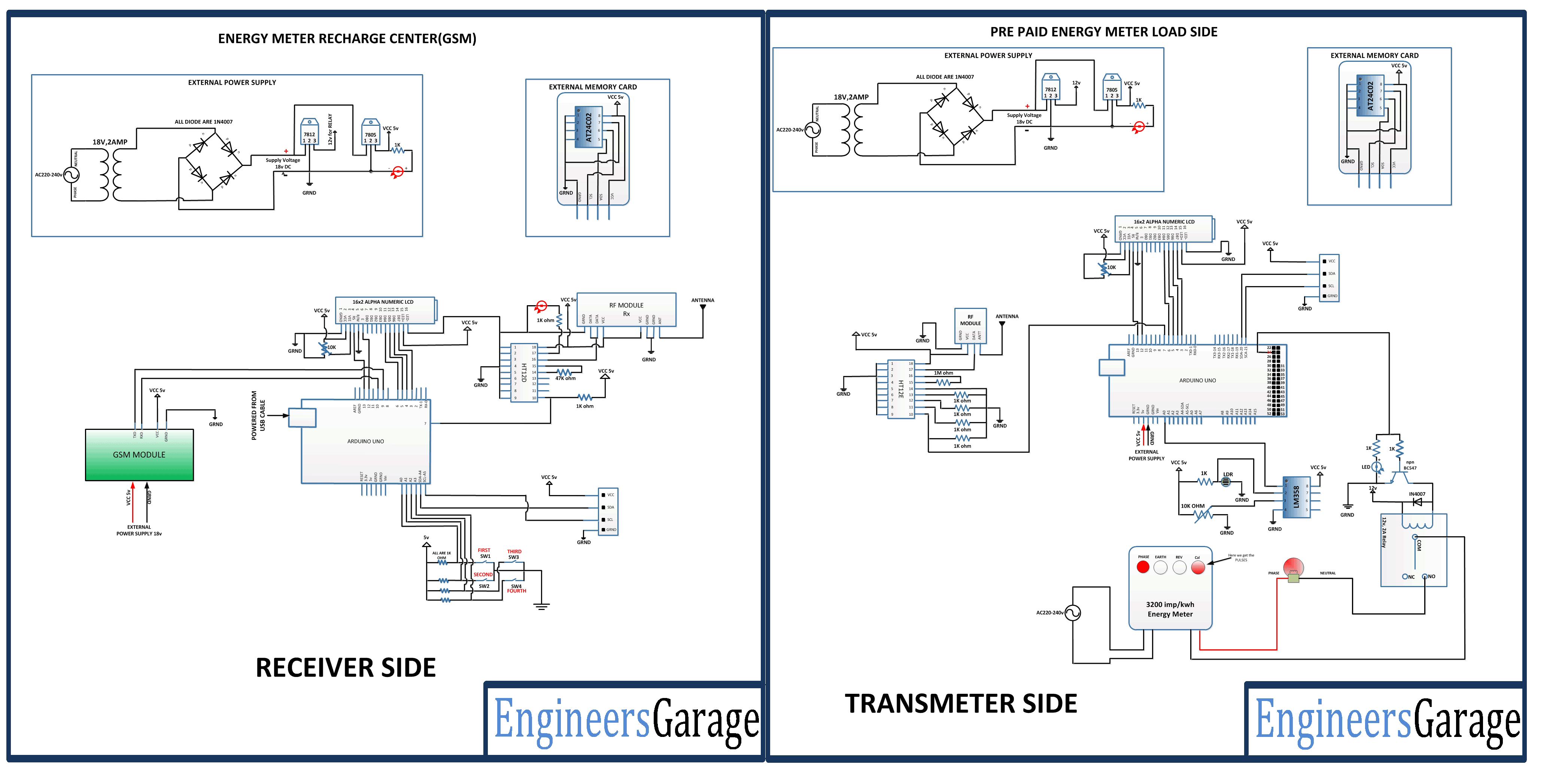 |


