In the previous article, we discussed the basics and working principles of an inductor. We also learned about some common types of inductors such as solenoid coils, toroids, pot cores, and transmission line inductors. Inductors come in a variety of other types based on construction. When selecting an inductor for a given circuit, it is important to understand its various specifications and non-ideal characteristics.
These electrical specifications remain common among all types of inductors. Different types of inductors are just application or circuit specific constructions. Unlike capacitors or resistors, it is relatively easy to select an inductor type for a given application. The different types of capacitors and resistors have somewhat overlapping areas of application. As discussed in previous articles, several factors are responsible for your selection.
The different electrical specifications are useful for determining the function and efficiency of an inductor for a particular circuit or application, rather than selecting a specific type or inductor. The main technical specifications associated with inductors are as follows:
Nominal Inductance – The first specification that needs to be considered is the nominal inductance of an inductor – or the value of inductance that the inductor must offer at a given frequency and voltage. Nominal inductance is usually expressed in Microhenry, Millihenry or Henry. Generally, engineers are given the required inductance value in the datasheet when using an IC or in case of analog circuits; or need to derive the required inductance value according to the application or circuit. For example, an engineer may need to derive the inductance value required for a filter circuit. The inductance of an inductor depends on the material used as the core, shape of the core, number of coil turns, shape and size of the inductor.
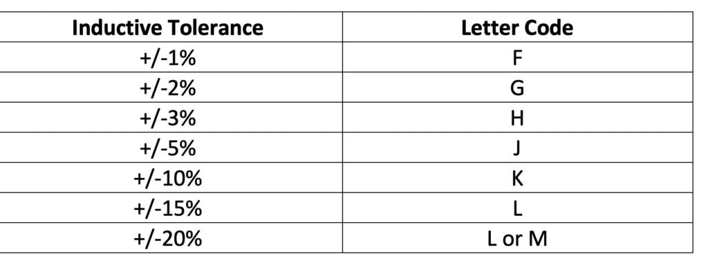
Tolerance – Inductance, like capacitance, is a dynamic property. It can change with signal frequency, temperature and current. It is therefore always important to consider the inductive tolerance of an inductor. Tolerance is the maximum variation in inductance value under all possible test conditions. Ideally, the inductance should not vary beyond the indicated tolerance under any condition, otherwise it may be damaged due to improper use or application. Inductors can have a tolerance of +/- 1%, +/- 2%, +/- 3%, +/- 5%, +/- 10%, +/- 15% or +/- 20%. Tolerance is indicated by the following letters:

Saturation current – As already discussed, inductors that use ferromagnetic cores beyond a critical current level experience a drop in inductance. This current level is denoted as Saturation Current . The drop in inductance can be up to ten percent in inductors designed with ferrite cores and up to 20 percent in inductors using fed iron as the core. This drop in inductance is the result of the core material being limited in storing a certain maximum amount of magnetic flux. The current carrying capacity of an inductor depends on the thickness of the coil, and any coil can carry current beyond the saturation level. A current large in excess of the saturation current can damage or fracture the core of an inductor, so it is essential to note the saturation current rating of an inductor. The saturation current of a selected inductor must be at least 1.5 times the maximum current to which the inductor can be exposed in the circuit. It is important to take into account any pulsating currents when choosing a saturation current level, as well as examining how inductance varies with current to ensure efficient and expected inductor operation in a circuit.
Curie Temperature – As the current increases beyond the saturation level, the core of the inductors heats up. It can become damaged or fractured, leading to the loss of its magnetic properties when it gets hot enough. The core temperature beyond which the inductor loses its magnetic properties is called Curie Temperature . Once an inductor loses its magnetic properties, it is nothing more than a connecting wire. It is important to first keep current levels below saturation current so that the inductor never heats up to the Curie temperature.
Ambient Temperature Range – This is the ambient temperature range within which the inductor can operate without being damaged.
Operating Temperature Range – This is the temperature range that an inductor can withstand without losing its magnetic properties or becoming damaged. Typically, the highest temperature limit in the operating temperature range is the Curie temperature. The operating temperature range is always greater than the ambient temperature range because when current flows through an inductor, it must heat up compared to the ambient temperature.
Saturation Magnetic Flux Density (B Sitting ) – This is the maximum flux density of the inductor core. This property is important in determining the maximum magnetic energy an inductor can store at any given time.
Maximum DC Current – This is the maximum level of direct current that can pass through the inductor without any damage. It is based on the maximum temperature (Curie temperature) that an inductor can withstand at maximum ambient temperature. For low frequency signals, it is directly comparable to the maximum RMS current of the signal. For high frequency signals, saturation current is a better reference.
Incremental Current – The DC current through the inductor that causes a drop in inductance by five percent compared to the inductance at initial zero DC bias is called incremental current . Beyond this level of DC bias current, the inductance begins to drop significantly. The rate at which the inductance drops depends on the ferromagnetic core material as well as the shape of the inductor core. The drop in inductance remains linear for powdered iron cores, while it drops at nonlinear rates for ferrite cores.
Maximum DC Resistance – This is the maximum resistance offered by the inductor coil with DC current or the unwanted resistance of the inductor. In designing an inductor, the maximum DC resistance must be minimized. This property always needs to be considered when determining the energy efficiency of an inductor in a given circuit.
Quality factor (Q factor) – The Quality Factor (Q) is an indication of the operational losses of the inductor. It is defined as the ratio of inductive reactance to effective resistance. Both inductive reactance and effective resistance are functions of signal frequency. This is why the quality factor is always indicated in the technical sheets for a given test frequency. The higher the quality factor, the more energy efficient the inductor.
Self-Resonant Frequency (SFR) – Due to the turns of wire in the inductor coil, there is always some capacitance distributed across the inductors. This distributed capacitance is also a function of frequency. At a certain frequency, the capacitance and inductance of an inductor become equal and cancel each other out. This is called Self-Resonant Frequency (SFR) . At this frequency, the inductor does not have any inductance effect; instead, it behaves like pure high-impedance resistance. In SFR, the inductor quality factor drops to zero. The distributed capacitance is modeled as a capacitance parallel to the pure inductance of the inductor. In addition to the self-resonant frequency, the capacitive reactance due to the inductor coil dominates the inductive reactance of the inductor.
Inductance Temperature Coefficient – The Inductance Temperature Coefficient indicates the rate of change in the inductance of the inductance per unit centigrade. It is expressed in variation of “parts per million” per centigrade (PPM/°C). The temperature coefficient is generally positive until the inductor heats up sufficiently at saturation current. Beyond the temperature in the saturation current, the temperature coefficient becomes negative. The temperature coefficient remains linear for powdered iron cores, although it is generally nonlinear and changes significantly for ferrite cores. In the inductor data sheets, the change in inductance is indicated in relation to the current and not the temperature, as the current is easily measurable in comparison with the inductor temperature. Therefore, the graphical curve of “typical inductance versus current characteristics” should be examined on a data sheet to check for any effects of temperature on inductance.
Temperature Coefficient of Resistance – Just like inductance, the DC resistance of the inductor also changes with temperature. However, this DC resistance will never exceed the maximum specified DC resistance for the inductor until the inductor is damaged. The temperature coefficient of resistance indicates the rate of change of the DC resistance of the inductor. It is expressed in PPM/°C. Since any wire always has a positive temperature coefficient, the temperature coefficient of the resistance is also always positive.
Electromagnetic interference – Electromagnetic interference from an inductor refers to the magnetic field radiated from the inductor. This may produce additive or subtractive mutual inductance with other inductors in the vicinity or may lead to unwanted interference with other magnetically sensitive components in the circuit. Electromagnetic interference can be useful when some mutual inductance is needed in a circuit. Otherwise, in most cases, it is undesirable and can influence inductor selection for a given design and PCB layout of a circuit.
Impedance – Impedance is the effective resistance of the inductor to alternating current. It is the combination of DC resistance and reactance (inductive reactance and distributed capacitive reactance) of the inductor. It is usually indicated by the typical impedance characteristics graph in inductor data sheets. The graph is drawn between the inductor impedance and the signal frequency.
Activity 10
Try to discover all the technical specifications that we discussed in this inductor technical sheet.
Check out online marketplaces for electrical and electronic components and review different filters to select an inductor.
In the next article, we will discuss different types of inductors.