Basics of DC Series Motors
DC series motors consist of a field winding connected in series with the armature winding. This unique configuration allows them to produce high torque at low speeds, making them suitable for traction, cranes and transport systems. Effective speed control of DC series motors is crucial to optimizing performance, energy efficiency and safety. By adjusting the speed, you can ensure that the engine operates efficiently under different load conditions.
Speed control methods
Speed control of a DC series motor can be done using any of the following techniques:
-
Flow control method and
-
Anchor Strength Control Method
Flow Control Method
By continuing this method, the flow can be varied and the speeds of the DC series motor can also be varied. A change in flow can be achieved in one of the following ways.
- Field deflection method
- Anchor Deflection Method
- Field control method utilized and
- Parallel Field Coils
Field deflection method

The above figure shows that an adjustable resistor is connected in parallel with the field winding in series. Here the adjustable resistance is called field shifter. This causes a certain shutdown rate to be ignored. This causes the area to become weak and the engine speed to increase. The minimum that can also be achieved is the resulting zero current level in the field diverter. The minimum speed is nothing more than the nominal speed of the engine. Therefore, this method only provides engine speeds higher than normal. This technique is used in traction work.
Anchor Deflection Method
In the flow control method, the motor speed can only be achieved by the speed tInspeedcan; we can achieve a speed below the normal speed by connecting the adjustable resistor in parallel with the armature. Here the adjustable resistance is I; an anchor diverter; hence the name. This diverts some of the line current, reducing the armature current. Therefore, the engine speed decreases because N∝(1/Φ). We can achieve a motor speed below the normal speed by varying the adjustable resistance (armature diverter). 
TarateField control method
In the plugged field control method, the speed of the series motor can be increased by reducing the field. Series field control is shown reducing the field in Figure 1. The “airport circuit at any point in the winning area will be turned on” switch This will cause the flow to decrease and the speed to decrease. Motor runs at normal speed with full turns of the series field winding because the series field turns are cut off. With this method the normal value can be achieved.

Archived method parallelization
By rearranging the number of cigarettes, different methods can be achieved, as shown in the figure. This technique is generally only used on fan motors.
Voltage regulation
By varying the voltage applied to the armature, the speed of the motor can be adjusted. This method is simple and effective, but may reduce efficiency at lower speeds due to increased armature current.
Armor resistance control
Adding an external resistor to the armature circuit reduces the effective voltage across the armature, thus controlling the speed. This method allows for smoother control, but also results in power losses in the resistors.
Helicopter control
The engine's electronic chopper circuits quickly turn the engine supply voltage on and off, effectively controlling the average voltage and speed. The chopper control is efficient and allows precise speed adjustments.
Thyristor control
Thyristor-based regulators such as B. Phase angle controllers regulate the armature voltage by controlling the conduction angle of the thyristors in the circuit. This method is suitable for high-performance applications.
Factors to consider
Load fluctuations
Different applications have different load requirements. Speed control methods must accommodate load changes without compromising efficiency or stability.
Efficiency
Choosing an appropriate cruise control method is important to maintain balance as the benefits of cruise control must be balanced.
Overheating and cooling
The speed controller controls the engine temperature. To prevent the engine from overheating, suitable cooling measures may be necessary.
Control complexity
Although modern control methods provide precision, they can also increase the complexity of the control system: the choice of applications depends on the application requirements and available resources.
Anchor Resistance Control Method
This method is often used to evaluate the speed of DC series motor. With this method, speed control below normal speed can be achieved. An adjustable resistor connected in series is shown in Fig. Varying the adjustable resistance puts the .v at risk. You vary the adjustable load by varying the adjustable resistors. By changing the resistance, the speed can be adjusted below the resistance by the resistance controller. Normal rated speed can be achieved.
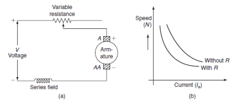
Although this method allows for reduced speed control, this is not significant for in-line engines as they are used in floating speed applications. The waste of energy in series resistors for many application actions in series motors is not very serious later in these applications. Speed control is used most of the time to reduce speed under light load conditions and is occasionally used while the engine is running at full load.
Conclusion
To master the speed control of DC series motors, it is necessary to understand the typical characteristics and select appropriate control methods based on the application's varioloid control strategy. These engines can provide efficient and reliable performance in a variety of industrial and automotive applications.