The circuit presented here is used to transmit and receive low frequency pulses using IR modulator and demodulator . The IR modulator takes low frequency pulses as input. It modulates them on the 38 KHz carrier and transmits them through the IR LED as 38 KHz IR light. On the demodulator side, the IR sensor detects (receives) 38 KHz IR light. It demodulates these 38 KHz pulses and recovers transmitted low frequency pulses. A pulse generator is constructed using IC555 to generate low frequency pulses. IR modulator is also built using IC555 and TSOP1738 IR sensor is used as IR demodulator.

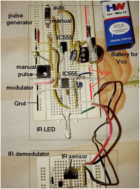
Figure 1: Prototype low frequency IR modulator and demodulator based on 555 IC and TSOP1738
Circuit connections:
The circuit is divided into 3 sections.
1. Pulse generator
2. IR Modulator
3. IR Demodulator
Pulse Generator:
It generates low frequency pulses that must be modulated and transmitted. The circuit is composed around IC555. A 10K pot R1 is connected between Vcc and pin no. 6. Its slider terminal is connected to pin no. 7 as shown. A 100 µF capacitor C1 is connected between pin no. 6 and land. R1 and C1 are timing components. Not pin. 2 can be connected to pin no. 6 or can be connected to the button via the slide switch as shown. Output pin 3 is connected to enable pin 4 of the IC555 modulator and also drives the LED through current limiting resistor R2. Pin 8 is connected to Vcc and pin 1 is ground to provide bias. Pin 4 is connected to Vcc to enable circuit operation. Pin 5 is grounded through 100 nF capacitor C2.
IR Modulator:
IC 555 is configured in astable mode with R4, R5-R6 and C2 as timing components. The values of these components are selected to produce 38 KHz pulses at the output. The output of this IC drives the IR LED through the current limiting resistor R7. The equation for output frequency is
F = 1.44 / (R4 + 2×Rp)×C2
Where Rp = R5×R6 / (R5+R6)
So Rp = 3300/2
EF = 1.44×10 -9 / (470 + 3300)×10
= 38.2×10 3
IR Demodulator:
The TSOP1738 IR sensor works as an IR demodulator. Bias is given to its pins 1 and 2, respectively. Its output pin 3 drives the LED through the NPN Q1 transistor connected in the switch configuration. The final output is obtained through the Q1 collector.
Here are snapshots of circuits built on two different circuit boards.

Figure 2: Image showing IR receivers and transmitters in low-frequency IR modulator and demodulator circuits
Circuit Operation
· The pulse generator generates low frequency pulses of less than 1 Hz. In manual mode, the IC555 is configured in monostable mode and generates a single pulse when the button is pressed. In automatic mode, the IC555 is configured in astable mode and generates continuous pulses. Its frequency can be varied by varying the potentiometer
· These low frequency output pulses are given to IC555 modulator at pin 4. It generates 38 KHz burst (of pulses) when pin no 4 is high. This is shown in the figure below with waveforms. These 38 KHz pulses are transmitted by IR LED. Therefore, the low frequency pulses are modulated by 38 KHz pulses and are transmitted as infrared light.
· IR sensor detects 38 KHz IR light. Its output decreases when it receives 38 KHz infrared light and vice versa. Therefore, at the sensor output we obtain the exact inverted output of the transmitted pulses. Finally, when these inverted pulses are given to the input of the transistor, it inverts this input again and generates the same pulses at the output (similar to the transmitted pulses).

Figure 3: Waveforms for low frequency pulse in modulator and demodulator circuits
Circuit diagrams
| Circuit Diagram-555-Ic-Tsop1738-Based-Low-Frequency-Ir-Modulator-And-Demodulator |