There are different types of speakers such as Tweeters, Mid-range Speakers, Sub-Woofers and Woofers which can reproduce voice only in their own specific frequency bands. In an audio playback device, all audio signals are separated into different bands and applied to the corresponding type of speaker. Tweeters are typically powered with frequencies above 5 kHz, Mid-range speakers are powered with frequencies in the range of 300 Hz to 5 kHz, Sub-Woofers are powered with frequencies from 300 Hz to 40 Hz, and Woofers are powered with frequencies below 40 Hz.
The entire audible speech spectrum extends from about 20 Hz to 20 KHz and there is no speaker design that can reproduce all of these frequencies with the same effect. Woofers are made to produce subsonic sounds (below 20 Hz) and there are musical instruments that can produce frequencies above 18 KHz. To reproduce all these sounds, different types of speakers are fed with their own band of frequencies extracted from the music.
The filter circuits used on the output side of the audio device that filter different bands of frequencies and use them to drive different types of speakers are called Audio Crossover Circuits . Three-way crossover circuits are very common on the output side of audio devices that filter frequency bands for Tweeters, Mid-Range Speakers and Sub-Woofers. This tutorial discusses the design and implementation of two-way audio crossover circuit using active filters for quality filtering.

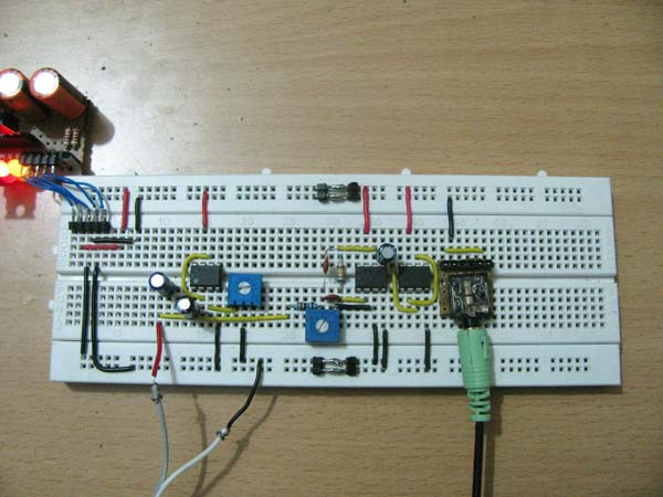
Fig. 1: Bidirectional active audio crossover filter circuit on breadboard
The Two-way audio crossover circuits are used to drive the midrange speakers and subwoofers separately. The mid-range speakers are fed with frequencies in the range of 300 Hz to 5 kHz, and the Sub-Woofers with frequencies of 300 Hz to 40 Hz. As musical sound normally lies around the maximum frequency of 5 to 8 KHz, for driving the midrange speakers a high-pass filter with a cutoff frequency of around 300 Hz is sufficient. The bass beats of music appear in the Sub-Woofer range and a bandpass filter can be used to separate these frequencies from all audio signals. The bidirectional crossover circuit can be considered as a combination of HPF (high pass filter) and BPF (band pass filter) as shown in the following block diagram;

Fig. 2: Bidirectional Active Audio Crossover Filter Circuit Block Diagram
HPF and BPF can be realized using only passive components like inductors and capacitors, but here active filter circuits are used to improve the quality of filters. Again for HPF, an active synthetic inductor based filter is used to avoid a bulky inductor from the circuit. The BPF is designed based on an MFB filter for a simple and good quality circuit.
Synthetic Inductor Circuit
The basic concept of the synthetic inductor circuit is to use a capacitor and invert its properties so that it behaves like an inductor. The advantages of this circuit over real inductors are very low internal resistance, easily varying the inductance value over wide ranges, possible to design high quality filter circuits etc. Circuit diagram of a synthetic inductor circuit is given below;

Fig. 3: Circuit Diagram and Equivalent Circuit of Synthetic Inductor
Here the property of capacitor 'C' in the above circuit has been inverted with the help of unity gain operational amplifier circuit. The value of the inductance depends on the values of the resistors R1, R2 and also the capacitor C. The inductance of the synthetic inductor circuit is given by the following equation;
L = R1 * R2 * C
High frequency filtering can be accomplished using a single capacitor and a synthetic inductor connected in series in which one end of the inductor is grounded, the input is fed by the free end of the capacitor, and the filtered output is taken from the point where the capacitor and the inductor are connected in series. The circuit diagram and equivalent circuit of synthetic inductor based high pass filter is given in the following diagram;

Fig. 4: Circuit diagram and equivalent circuit of high pass filter based on synthetic inductor
The circuit contains a series capacitor 'Cf' which forms a high pass filter with the synthetic inductor circuit. If the inductance of the synthetic inductor is 'L', then the passband of the high-pass filter starts at the frequency given by the following equation;
Most audio frequencies, except bass frequencies, appear above a mid-frequency of 700 Hz, and therefore the high-pass filter is designed for a cutoff frequency of 700 Hz.

Fig. 5: Circuit diagram of high pass filter designed for frequency clipping
MFB filters are very commonly used in circuits due to the fact that they provide reasonable performance with the simplest circuit. They can be designed to achieve narrow bandwidth and high gain. They are suitable for designing bandpass filters as the bandwidth and midband frequency can be easily adjusted or varied. These circuits have an amplifier with more than one feedback and hence the name. The circuit diagram of an MFB bandpass circuit using a single resistor and capacitor feedback is given below;

Fig. 6: MFB bandpass circuit diagram with single resistor and capacitor feedback
Equations relating component value to gain, Q factor, bandwidth, and midband frequency are given below;
Since this filter will be used to drive a speaker, a buffer circuit needs to be added at the output of the MBF bandpass filter that will drive the speaker without affecting the characteristics of the filter. The buffer can also be easily created with another op amp. An MFB bandpass filter with Fm = 70, Q = 15, Am = 100 has been designed and the complete circuit is given below;

Fig. 7: Circuit diagram of MBF bandpass filter with buffer circuit
A synthetic inductor based HPF and an MFB based BPF were designed separately and to make an audio crossover circuit it is necessary to connect the input of both the circuits and feed the audio to that common input point of both the circuits. The complete circuit diagram of the Audio Cross-over circuit is given below;

Figure 8: Two-Way Active Audio Crossover Filter Circuit Diagram
The audio input is powered by a PC and the filtered audio in this experiment is demonstrated in the video using a normal headphone, as the headphone speakers are designed for good quality reproduction of both high-end sound. frequency and low-frequency bass.
Video: