In this tutorial I will teach you how to control DC motor speed using stm32 microcontroller and half h bridge control IC l293d. DC motors are common motors you see in your homes (DC water pumps, DC fans), toys, etc. DC motors rotate at a constant speed, but their speed can be varied and controlled using certain techniques. One of these techniques and the most popular is to provide it with a variable voltage. By variable voltage I mean providing less amount of voltage (power) than the maximum rating of a specific DC motor. Just like our ceiling fans (work on AC voltage), the rotation speed is controlled by varying the potentiometer (variable resistor) connected to the button socket. The resistor varies the power when we turn its knob in any direction.
Variable resistor is a good choice for controlling motor speed. But if we want to insert some control logic (e.g. change the direction of rotation of the motor) or precisely control the rpm of the motors (resolutions per minute), then the variable resistor technique cannot fully meet our needs. To achieve superior logic, pwm (pulse width modulation) technique is best suited. In pulse width modulation, the constant input voltage to the motor is divided into subcycles to reduce the amount of input voltage.
In this project our objective is to control the speed of the motor with stm32 microcontroller. Pwm technique is used in the project to control the speed and direction of the motor. The pre-assembled St32f103c8t6 microcontroller board is used in the project. STM32CUBEMX is used for STM32F103C8T6 GPIO microcontrollers, timers setting. Keil arm mdk 5 is used to write and compile the project code. The code is written using HAL stm32 libraries. If you are new and don't know stm32cubemx, keil arm mdk 5 and HAL libraries, I advise you to first do the getting started tutorial with stm32cubemx and keil arm and HAL libraries. Just click the button below to do the tutorial.
Getting started stm32cubemx, keil arm and HAL libraries
I will control the speed of two DC motors connected to the l293d half h ic bridge. What is l293d? Microcontrollers work on TTL logic from 3.3 to 5 volts. Where DC motors run from 5 to +24 volts. It is not possible to drive motors directly from the microcontroller output pins. The output pins of the microcontroller can only supply 5 volts and 25 mA of current, which is not suitable for DC motors to start rotation. Stm32 microcontrollers work on 3.3 volt TTL logic. For this project I am using 12 volt DC motors that require 200 mA of current for constant rotation. So we need an external circuit to drive the motor using stm32 microcontroller.
Transistor or Mosfet as external circuit to drive, control the speed and direction of the DC motor
An external transistor or mosfet is the best choice to drive a 12 volt motor using stm32 microcontroller. The base of the transistor, MOSFET, is connected to the STM32 output pin and the motor will be inserted between the collector of the transistor. A variable PWM signal to the transistor base of the STM32 output pin can easily control the rotation speed of the DC motor. But we also need to change the direction of the motor, which is not possible in this configuration.
Half-bridge h circuit for DC motor direction control
In half-bridge h circuit, two transistors are used to control the direction of rotation of the DC motor. Making a half-bridge h circuit with DC motor power requirements is not an easy task. L293d is a pre-assembled IC containing two half-h bridge configurations. We can drive, control direction and speed of two DC motors easily with l293d ic motor driver.
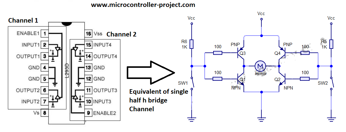
Half h L293d Single Bridge Channel Equivalent Circuit
To learn about the pinout and the purpose of each pin on the l293d you need to do another tutorial. I explained the l293d circuit and its operation in depth in the tutorial. The tutorial will help you understand the circuit diagram of the project below. Click the button below to do the tutorial.
Project working
I will control the direction of rotation of the DC motors and their speed in the project. For this I decided to connect four buttons as input. The buttons will control the direction and speed of the motors. I will discuss the purpose of each button later. For four buttons as input, I need four gpio's from the stm32 microcontroller declared as input. I declared pins 6, 7, 8 and 9 of Port B as input. I also activated the pull up resistors associated with these pins.
To control the direction of two DC motors through half-bridge circuits, I need four controls. Basically, four pgio pins of the microcontroller are required to control the rotation direction of two DC motors. I declared four pins 0, 1, 2 and 3 of Port A of stm32 microcontroller as output.
Finally, to control the motor speed, I need two PWM signals. I will use pins 0 and 1 of Port B as pwm sources. Generating pwm using stm32 is not an easy task. It is necessary to take care of many restrictions. I have another tutorial on how to generate pwm with stm32 microcontroller. I have discussed all restrictions on frequency, duty cycle and counter etc. in that tutorial. Please follow this tutorial before proceeding. If you don't follow the tutorial, you won't be able to understand the code below.
Stm32 pwm generation formula calculations and constraints
If you followed the tutorial above, you probably now know how to generate the desired pwm with the stm32 microcontroller. To control the speed of the DC motor, I have to vary the pwm signal. Varying the pwm signal is not a difficult task if you followed the above tutorial. Enemy varying the pwm signal you need to calculate some more variables. In this project I am generating a variable duty cycle pwm signal at a frequency of 50 Hz. I actually calculated these values for another project (Servo motor with stm32 microcontroller) and used these values in this project. You can view the project settings if you wish. This will help you in stm32cubemx pwm settings.
Stm32cubemx settings for this project borrowed from another project
Stm32cubemx gpio settings and pwm timer settings are given below. You must follow the tutorials above to understand each constraint and how they are calculated and entered into stm32cubemx.

Stm32cubemx pwm timer 3 and gpio settings
I am using the internal 8 Mhz oscillator of stm32f103 microcontroller for clock source for gpio pins and for pwm generation. These settings are required to generate the 50 Hz frequency pwm signal as discussed above.

STM32F103 Microcontroller PWM Clock Settings on STM32CubeMX
For pwm I am using pins 0 and 1 of port B of the stm32. With both pins of the microcontroller timer-3 is associated. With pin 0 timer 3 channel 3 is linked and with pin 1 timer 3 channel 4 is linked. We have to activate these channels before we start working with them. How to activate channels? Settings are given below.

Stm32 timer 3 channel pwm settings on stm32cubemx
Design circuit
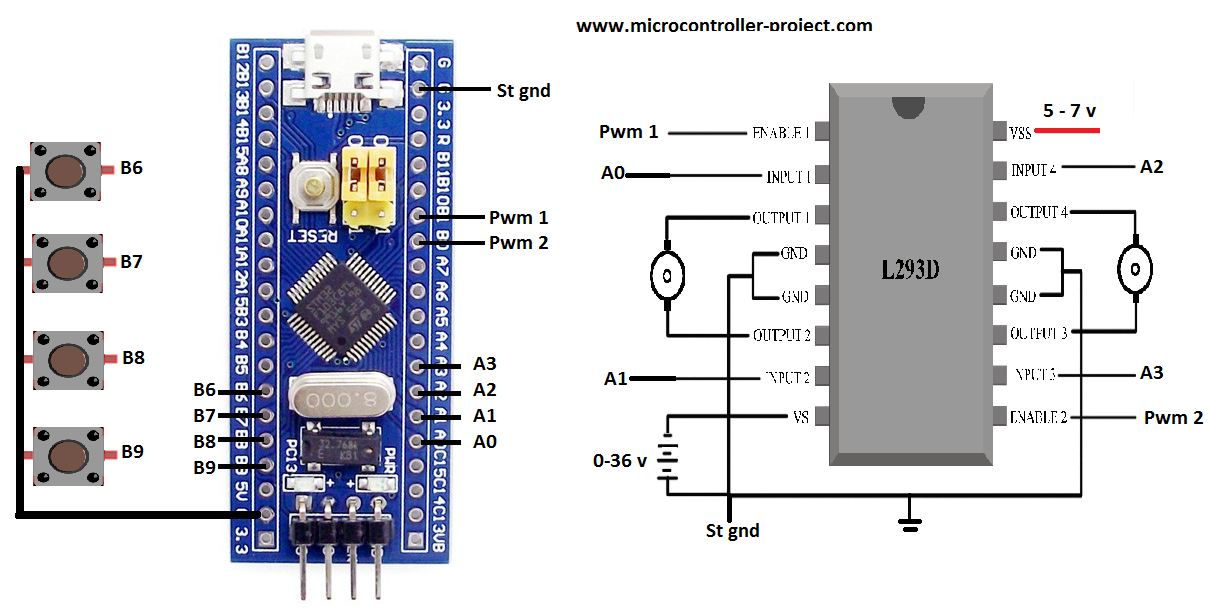
Port A pins A0 and A1 are used to control the direction of motor-1. Pin A0 of the microcontroller is connected to input 1 of l293d and pin A1 is connected to input 2 of l293d. Pwm signal is provided to enable motor pin 1 or channel 1 of l293d. Pin 1 of port B of Stm32 is connected to enable 1 of l293d. Similarly, pins A2 and A3 of Port A of the stm32 microcontroller are used to control the speed of motor 2 or channel 2 of the l293d. Pin A2 of stm32 is connected to input 4 of stm32 microcontroller and pin A3 of stm32 is connected to input pin 3 of channel 2 of l293d. The channel 2 enable pin of the l293d is connected to the B0 pin of the stm32 microcontroller.
Our 12 volt motors are connected to the output pins of the L293D. Motor 1 is connected to the channel 1 output pins and motor 2 is connected to the channel 2 output pins of the L293D motor driver. The grounding pins are grounded.
Note: The grounding of the stm32 microcontroller power supply and the l293d motor power supply must be commonly grounded for circuit completion and proper functioning.
DC motor speed and direction control with stm32 microcontroller and l293d motor driver
Input button functions
- B9 – Pressing the B9 button will switch the direction of rotation of the DC motor. If moving forward, pressing the B9 button will change the direction back.
- B8 – Pressing the B8 button will set the pwm duty cycle to 75% and decrease with engine rotation speed.
- B7 – Pressing the B7 button will set the pwm duty cycle to 50%. The DC motor rotates at half the speed of the maximum.
- B6 – Pressing the B6 button will set the pwm duty cycle to 25% and decrease the rotation speed further.
Coming to the code. The main logic of the code is before and between the while loop 1. If you have gone through the above tutorials on Pwm and stm32cubemx how to get started, you can easily understand the code instructions below. The instructions are the same as the previous tutorials, only the sequence of instructions is changed as desired in the project.
In the above code, the first instructions before while 1 loop start both DC motors and pwm signal are output with 100% duty cycle. During 1 loop, each button press is checked continuously. If any button is pressed, the corresponding function (direction reversed, speed changed) will be executed. I hope the above code is easy for you if you have gone through all the tutorials listed in the post.
Future work:
With the same code and logic above you can not only drive DC motors but also servo motors. In the circuit you have to change some settings such as input voltage for l293d to drive the servo motor (5 to 12 v). Servomotors operate at a frequency of 50 Hz and have a duty cycle between 1 millisecond and 3 milliseconds. We generate pwm at the frequency of 50 Hz. So you can connect a servo to the output and check if the code works (it will definitely work). You can also dim an LED by connecting it to the l293d output with the same code, circuit above. You may need to correct the direction and not change it to LED. Since the polarity of the LED cannot be changed.
Download the project code. The folder contains stm32cubemx and keil arm ide project files. All project libraries and dependencies are included in the folder. Please provide us with your feedback on the project.
Code/files