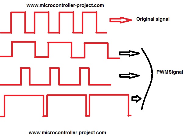
PWM, in simple words, changes the output voltage at a specified pin to which it is applied by varying the duty cycle of the output waveform. The frequency and duty cycle of PWM signal can be easily varied using 8051 microcontroller timers . The figure below will enlighten you about PWM signals and duty cycle. The duty cycle of the original signal varies in the diagram below.
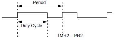
What exactly is the duty cycle?
Motor speed control with 8051 microcontroller – Project requirements
- 8051 Microcontroller(89c51 or 89c52)
- Crystal (11.0592 MHz)
- Capacitors 2 (33pf)
- 9 push buttons
- DC Motor – Fan (small toy motor)
- Power supply (5v)
- L293D (DC motor driver)
Now, how to generate these delays using 8051 microcontroller timers (89c51,89c52)? There are two timers in 89c51 microcontroller, Timer-0 and Timer-1. You can use them for delay purposes or to count an event, etc. You can use these timers in four modes. I'm using them in 16-bit mode. To learn more about timers, their modes and initialization follow the tutorial
- 8051(89c52,89c51) Microcontrol Timers
8051(89c52,89c51) are 8-bit microcontrollers. But you can use your timers as 16 bits. To load 16-bit values into timers you use two registers THx and TLx associated with the timers. Where THx represents Timer High Byte and TLx represents Timer Low Byte (Note x is 0 or 1 depending on the timer you want to use). Here I am using Timer-0, so I will use registers TH0 and TL0.
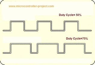
My base duty cycle is 200 us which means at 100 us the duty cycle will be 50%. 50% duty cycle means that the positive and negative signals have the same length (time). You can see two (digital) sine waves with duty cycles of 50% and 75% in the figure on the left. Notice the difference between the two waves.
I calculated the delay for 00, 20 us, 40 us, 100 us, 160 us, 180 us, 500 us, 800 us and 100 us and loaded the values obtained by the result into the TH0 and TL0 registers. The formulas for calculating delay are given below with an example.