In the previous tutorials, the MQTT protocol was implemented to configure data communication between Mobile and PC, PC and PC, and Mobile and Mobile. The true power of IOT protocols can only be achieved with real-life IOT devices. In this tutorial, a real-life IOT application based on MQTT protocol will be designed.
The Internet of Things aims to empower everyday objects with embedded electronics and IT infrastructure. It aims to connect these objects in real time with the Internet network and allow them to communicate with other co-located or remote objects. To communicate with each other, IOT devices need to follow protocols. An application developer needs to primarily take care of the implementation of application layer protocols, while typically the implementation of network and transport layer protocols remains in the hands of network administrators or network programmers. In this IOT project, MQTT protocol will be used to connect the designed IOT device to the Internet.
In this project, a simple home network (HAN) will be designed using ESP8266 Wi-Fi module. This home network can be controlled from a remote PC using the Internet. The home network designed in this project is more simplistic, with an Internet-controlled LED light. It is assumed that the remote PC controlling the LED light (Home Area Network) is installed in an office far from the house.
Therefore, the IOT device designed in this project is a simple LED light controller which is designed by interfacing the LED light directly with the ESP-8266 Wi-Fi module. The Wi-Fi module as well as the LED light are continuously powered with the help of a USB to serial converter. The Wi-Fi module needs to be loaded with firmware that can interpret data received over the internet and use that data to control the LED light. Arduino UNO is used to update the firmware code on the ESP8266 module. The ESP module can also be flashed with code using an FTDI converter like the CP2102. The firmware itself is written in the Arduino IDE.
The remote PC acts as another IoT device in the project. The PC connects to the ESP8266-based device through the MQTT broker. hiveMQ is used as MQTT broker in this project. The PC connects to the broker using a Chrome add-on – MQTTLens.
Required components –

Fig. 1: List of required components for LED light controller based on ESP8266 HAN and HiveMQ Broker
Required software –
1. ArduinoIDE
2. HiveMQ Broker
3. MQTTlens (chrome add-on)
Block diagram –

Fig. 2: Block diagram of ESP8266 based IOT LED controller
Circuit Connections –
Firstly, the ESP8266 board needs to be loaded with the firmware code. In this tutorial, the firmware code is written using Arduino IDE. It is loaded onto the ESP8266 board using Arduino UNO. A generic ESP8266 board is used in this project. This board does not have startup resistors, voltage regulator, reset circuit and USB serial adapter. The ESP8266 module operates with a 3.3V power supply with a current greater than or equal to 250mA. Therefore, the CP2102 USB to Serial Adapter is used to supply 3.3V voltage with enough current to run the ESP8266 reliably in all situations.
The ESP8266 Wi-Fi Module is a standalone SOC with integrated TCP/IP protocol stack that can access a Wi-Fi network. The ESP8266 is capable of hosting an application or offloading all Wi-Fi network functions from another application processor . Each ESP8266 module comes pre-programmed with AT command set firmware. The module is available in two models – ESP-01 and ESP-12. The ESP-12 has 16 pins available for interfacing, while the ESP-01 only has 8 pins available for use. The ESP-12 has the following pin configuration –

Fig. 3: Table listing the pin configuration of the ESP8266 ESP-12 Wi-Fi modem
The ESP-01 model is used in the project. The ESP-01 model has the following pin configuration –

Fig. 4: Table listing the pin configuration of the ESP8266 ESP-12 Wi-Fi modem
The module's Chip Enable and VCC pins are connected to 3.3V DC while the Ground pin is connected to common ground. The chip's enable pin is connected to VCC via a 10K pull up resistor. The RESET pin is connected to ground via a tactile switch, where the pin is supplied VCC via a 10K pull up resistor by default. The Tx and Rx pins of the module are connected to the RX and TX pins of the Arduino UNO. The module's GPIO-0 pin is connected to ground via a tactile switch where the pin is supplied VCC via a 10K pull up resistor by default. These pull-up resistors act as voltage divider circuit that protects the ESP8266 board from high voltage. The Arduino board operates at 5V and also 3.3V, while the ESP8266 operates at 3.3V. Although the Arduino board itself is powered via its 3.3V power pin, this voltage divider circuit adds even more protection against any voltage spikes. The use of pull-up resistors increases the stability of the circuit. With these circuit connections, the Arduino board itself acts as a USB to serial adapter. The circuit connections between Arduino UNO module and ESP8266 for boot charging can be summarized as follows –

Fig. 5: Table listing circuit connections between ESP8266 Modem and Arduino Uno
During code compilation, the GPIO0 and RESET switches must be pressed. To load the program, the RESET switch must be released while the GPIO0 programming switch must be left pressed, so that the ESP can enter programming mode. After uploading the code, the programming key must also be released.
Write the firmware code in Arduino IDE and connect the Arduino board to PC via USB cable. Open the Arduino IDE and go to Tools->Port and select the Arduino board (Arduino UNO). It might look like /dev/ttyABM0 (Arduino/Genuino Uno). Select the correct port name. The port name may be different in different IDE configurations. Then open the serial monitor in the Arduino IDE by navigating to Tools->Serial Monitor and set the baud rate to 115,200 bauds per second. Pass the 'AT' and 'AT+GMR' commands to test the connection between the Arduino and the ESP-01 module. Try different settings for the serial monitor 'End of Line' option, such as NL and CR. Try different combinations until the ESP module starts to interact correctly with the serial monitor.
Download Python, PIP and ESPtool. Erase the preloaded firmware if the ESP module has any. Update the firmware code for the ESP-01 module by writing commands to the serial monitor according to ESPtool instructions. Check out the following link to write the proper command to update the firmware code using ESPtool –
ESPtool commands
To upload the program, the RESET switch must be released while the GPIO0 programming switch must be left pressed. After loading the code, the programming key must also be released. This way, the firmware code can be loaded into the ESP8266 using the Arduino board as an FTDI converter. It should be noted that all GND needs to be common to complete the circuit. GPIO2 is an alternative TX for bootloader mode.
Remove the connections. Now the ESP module is ready to be installed in the project circuit. In the project circuit, the ESP8266 interfaces with the CP2102 adapter and an LED.
The CP2102 is a single-chip USB to UART bridge. It is used to supply power to the ESP module. It can also be used for bootloading. A CP2102 IC has the following pin configuration –

Fig. 6: Table listing the pin configuration of IC CP2102

Fig. 7: Table listing the pin configuration of IC CP2102

Fig. 8: Table listing the pin configuration of the CP2102 IC
ESP board is connected to CP2102 for bootloading mode and usage purpose. For bootloading, the TX pin of the ESP-01 is connected to the RX pin of the CP2102 and the RX pin of the ESP is connected to the TX of the CP2102 so that both can send and receive data. The ESP8266-01 needs 3.3V power supply, so the VCC of the ESP is connected to the 3V3 of the CP2102 and the GNDs of both need to be connected to each other. The reset pin of ESP8266 along with the 10k pull-up resistor (bootstrap resistor) is connected to the RTS pin of CP2102. GPIO0 is a programming pin used to put the ESP-01 into programming mode. The GPIO0 along with the 10K pull-up resistor is connected to the DTR pin of CP2102. The CHPD pin of the ES-01 is pulled with a 10K resistor. The circuit connections between the ESP module and the CP2102 are summarized in the following table –

Fig. 9: Table listing circuit connections between ESP8266 ESP-01 modem and IC CP2102
After connecting the ESP module to the CP2102 adapter, the adapter must be connected to the PC and the ESP module must be loaded with firmware code in a similar way as demonstrated with Arduino.
After loading the code, the ESP module will automatically access the Wi-Fi point with the SSID provided in the firmware. An LED is connected to the ESP module. The LED anode pin is connected to GPIO2 with 220 ohm series resistor and the cathode pin is connected to GND. The ESP module is now ready to receive data from the internet via the Wi-Fi router and will control the LED accordingly.
On PC side install MQTTLens in Chrome browser. MQTTlens supports the MQTT protocol and can be used for publishing and subscribing to messages. The PC client must be assigned a unique client ID so that the MQTT broker can easily identify which client is publishing and subscribing to the topic and payload. Learn more about how to configure your PC as an MQTT client in the following tutorial –
How to configure PC and cell phone as MQTT clients
Learn about creating and subscribing to topics in HiveMQ broker and publishing messages to them in the following tutorial –
Communication between PC and cell phone using MQTT protocol via HiveMQ Broker
The following precautions should be taken while assembling the circuit –
1) ESP8266 needs 3.3V power to work, so do not supply 5V.
2) Some people say that ESP8266 does not have 5V tolerant inputs, but when Arduino was used as USB to serial adapter, it successfully provided serial communication. According to the ESP8266 datasheet, it was also written that the GPIOs of the ESP8266 can tolerate more power up to 6V.
3) If the espcomm_sync-failed.md error is shown while uploading the firmware code, first check the selected port on which the ESP module is connected and then check whether the module is entering bootloading mode or not. This can be checked by connecting the RX and GND pins of the converter to the TX and GND pins of the ESP. Then open a terminal and check whether the following message is received in the serial window or not.
ets January 8, 2017, first cause: 2, boot mode: (x, y).
4) Check whether the module pins are receiving adequate voltage or not using a multimeter.
5) If the module is working but starts burning after some time, there may be a current requirement problem. In this case, use an external power supply to supply 3.3V to the ESP8266.

Fig. 10: ESP8266 based IOT LED controller prototype
How the circuit works –
After loading the firmware and circuit connections, the ESP8266 module is ready to receive data via the MQTT protocol from the available Wi-Fi access point. The PC client is also ready to send control commands via the MQTTLens add-on. ESP8266 and PC clients communicate and send messages to each other through an MQTT broker called HiveMQ.
The ESP8266 client configures itself as a publisher for the topic “ESP8266/connection status” and as a subscriber for the topic “ESP8266/LED status”. The client PC configures itself as a subscriber to the topic “ESP8266/connection status” and as a publisher to the topic “ESP8266/LED status”. The ESP8266 client initiates the connection by publishing a 'Connected' message to the MQTT broker.
Upon receiving the message, the client PC may publish 'ON' and 'OFF' messages in the “ESP8266/LED status” topic. If the ON message is published by the client PC, it will be received by the ESP8266 client and its firmware code will interpret the message to turn on the LED light. If the OFF message is published by the client PC, it will be received by the ESP8266 client and its firmware code will interpret the message to turn off the LED light.
Programming guide –
The ESP8266 client is loaded with an Arduino sketch. An open source library is used for publishing and subscribing through the ESP client. In these public libraries nothing is changed or modified.
The ESP8266 client is connected to the home network by setting the SSID and password of the Wi-Fi router. The SSID and password of the Wi-Fi access point are initialized in the Arduino code as follows –
//Wi-Fi configuration
const char*ssid = “ABCDEF”;
const char* password = “qwerty”;
This code snippet can be initialized in configuration as well as defining a separate function with some other test cases. The following function is used to initiate the Wi-Fi connection.
WiFi.begin(ssid, password); //Start wireless connection
After connecting the ESP8266 to the Network, the ESP8266 will start connecting to the MQTT broker. The following code in the Arduino sketch is used to define the MQTT broker with which the ESP module has to communicate.
//The domain name of the broker or server
const char* mqtt_server = “broker.mqtt-dashboard.com”;
The ESP module based client is connected to the MQTT broker by calling the following function in the configuration.
client.setServer(mqtt_server, 1883);
Now the ESP8266 client is connected to the MQTT broker. It will register the topic with the MQTT broker and publish a message to the topic. The ESP8266 device will continuously publish the message about the topic “ESP8266/connection status” to the broker. Now, wherever the PC client subscribes to the topic, it will receive the “connected” message. The ESP8266 Client has also subscribed to the “ESP8266/LED Status” topic and will continuously wait for the message from the broker to control the LED. The following code snippet defines topic publishing and subscription on the ESP8266 client.
client.publish(“ESP8266/connection status”, “Connected!”); //for publication
client.subscribe(“ESP8266/LED Status”);
The ESP8266 client has registered or subscribed to the MQTT broker topic. So whenever it receives a message, it will call a message received function. This message received function is a callback function and the things that are written in this callback function will be called whenever the PC client publishes a message. The function will look for the payload data. If 'on' characters are received, the GPIO2 pin will be set to HIGH and the LED will begin to glow. If 'off' characters are received in the payload, the GPIO2 pin will be set to LOW and the LED will stop glowing.
// Handle the message we receive
// Here we are just looking at the characters of the received message
// If it is on, the LED will be on.
//If it is off, the LED will be off.
if((char)payload(0) == 'o' && (char)payload(1) == 'n') //on
digitalWrite(2,HIGH);
else if((char)payload(0) == 'o' && (char)payload(1) == 'f' && (char)payload(2) == 'f') //off
digitalWrite(2,DOWN);
Whenever the PC client publishes the ON message to the topic, this client will call this callback function and the LED connected to GPIO2 will be put into the ON state and when it receives an OFF message, the LED will be put into the OFF state.
In this way, the ESP8266 client and the PC client communicate with each other. This is just a basic code to check how two devices can communicate. In place of the LED, a temperature sensor can also be used that can provide the temperature and humidity of the environment. Even an engine can be controlled this way. There can be many things that can be done after establishing a connection between the two devices.
In the next tutorial – ESP8266 Based IOT Temperature Monitor Using Adafruit Broker, the ESP8266 client will be interfaced with a temperature sensor (as was interfaced with an LED in this tutorial) and the temperature readings will be observed on the PC client. In the next tutorial, instead of HiveMQ, Adafruit MQTT Broker will be used.
Project source code
### //Program to /* * File Name - ESP8266_with_PC_client.ino * Created: 3/20/2017 11:02:11 AM * Main Source Code for PC and ESP8266 clients communication with HiveMQ broker */ /* * Output Pins of the ESP8266 *GPIO02 - ledPin */ //Include libraries #include//Include the library for WiFI Initialization #include //Include the library for MQTT pubsub protocol // WIFI setup const char* ssid = "Replace it with the SSID of the Wi-Fi Network"; //SSID of the WIFI network const char* password = "Replace it with the password of the Wi-Fi Network"; //Password of the WIFI network //The broker or server domain name const char* mqtt_server = "broker.mqtt-dashboard.com"; // Create an ESP8266 WiFiClient class to connect to the MQTT server. WiFiClient espClient; //create the MQTT client objects PubSubClient client(espClient); void setup { pinMode(2,OUTPUT); //configure the led pin as OUTPUT Serial.begin(115200); //Set the baudrate of ESP8266 to show the process on serial monitor setup_wifi; //Initialize the Wifi //By setting server and messgae callback function, the client is ready to use //& 1883 is the listener port for the broker client.setServer(mqtt_server, 1883); client.setCallback(Received_Message); } /* * Function Name = setup_wifi *To establish the WIFI connection with ESP8266 */ void setup_wifi { delay(10); // We start by connecting to a WiFi network Serial.println; Serial.print("Connecting to "); Serial.println(ssid); //Connect to the WIFI WiFi.begin(ssid, password); // Wait until the connection has been confirmed before continuing while (WiFi.status != WL_CONNECTED) { delay(500); Serial.print("."); } Serial.println(""); Serial.println("WiFi connected"); Serial.println("IP address: "); Serial.println(WiFi.localIP ); } /* * Function name = Received_message * Client receives the message and functions accordingly * Input parameter = Topic, Payload and message length * Output parameter = void */ void Received_Message(char* topic, byte* payload, unsigned int length) { Serial.print("Message arrived ("); Serial.print(topic); Serial.print() "); for (int i = 0; i < length; i++) { Serial.print((char)payload(i)); } // Handle the message we received // Here, we are only looking at the characters of the received message // If it is on, turn the led will be on. // If it is off, turn the led will be off. if((char)payload(0) == 'o' && (char)payload(1) == 'n') //on digitalWrite(2,HIGH); else if((char)payload(0) == 'o' && (char)payload(1) == 'f' && (char)payload(2) == 'f') //off digitalWrite(2,LOW); Serial.println; } /* * Function Name = Reconnect * To establish the connection of ESP8266 with MQTT broker * and Will publish and subscribe to the topic */ void reconnect { // Loop until we're reconnected while (!client.connected ) { Serial.print("Attempting MQTT connection..."); // Attempt to connect if (client.connect("ESP8266Client")) { Serial.println("connected"); // Once connected, publish an announcement... client.publish("ESP8266/connection status", "Connected!"); // ... and resubscribe client.subscribe("ESP8266/LED status"); } else { Serial.print("failed, rc="); Serial.print(client.state ); Serial.println(" try again in 5 seconds"); // Wait 5 seconds before retrying delay(5000); } } } void loop { //When ESP8266 client will be connected to the broker, //then call the function reconnect and publish and subscribe the data from broker. if (!client.connected ) { reconnect; } client.loop; } ###
Circuit diagrams
| Circuit Diagram-ESP8266-ESP-01-Modem Based MQTT Server | 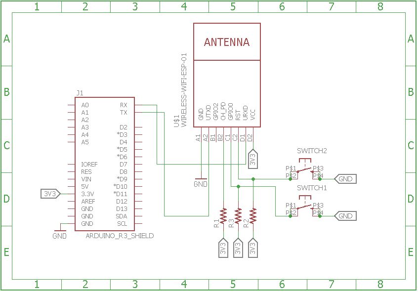 |
| Arduino MQTT client circuit diagram | 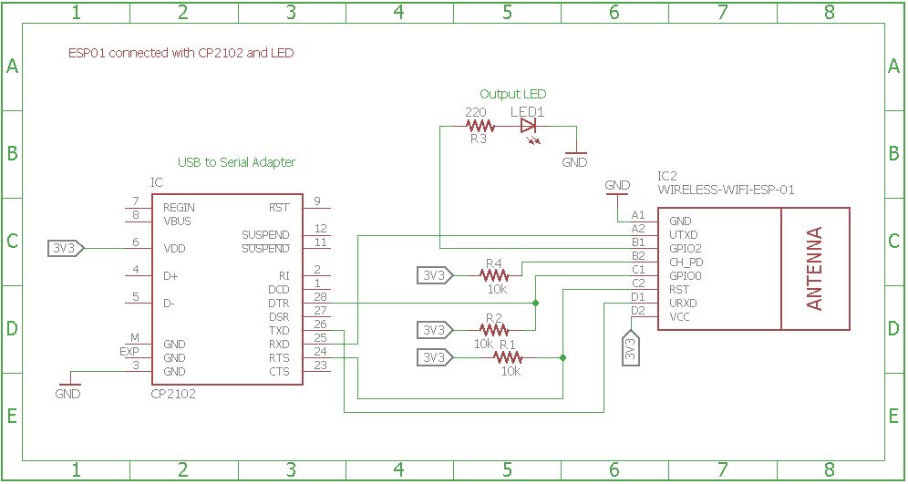 |