Servo is a special type of motor that converts electrical signals into shaft positions.
Servos can be broadly classified as industrial servos and hobby-grade servos.
Industrial servos are generally heavy-duty high-power AC or DC servos, widely used for precise robotic arms.
Hobby-grade servos are widely used in RC hobbies, such as RC planes, cars, helicopters, multirotors, boats, floating craft, etc.
They are mainly used to control control surfaces (RC planes) or for thrust vectoring mechanisms (hovercraft, boats, multirotors) or for steering mechanisms (RC cars).
Hobby level servos are classified as micro, standard and giant based on the torque they can provide, however their working principle is the same.B Based on the speed of operation, they are classified as analog or digital servos. Digital servos provide greater speed but consume more power.
The speed of a servo motor is defined as the time it takes the axis to move from 0 0 to 60 0 after applying the signal.
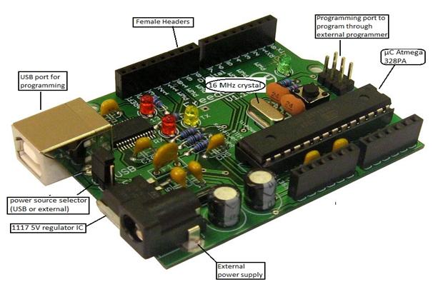
In this article we will use an ARDUINO clone board viz. FREEDUINO.
The freeduino board used is based on the arduino duemilanove board and uses microcontroller IC atmega 328PA.
The most striking feature of an Arduino platform is its ease of use, since Arduino was designed for artists rather than engineers, it becomes more interesting and fun to learn Arduino programming and make projects based on it.
Freeduino Advice:
Description
Description:
Servo is the most widely used actuator in projects such as robotic arms, RC plane, self-balancer, etc.
It uses a negative feedback mechanism to maintain axis position with minimal error.
The servo motor has three wires, unlike normal PMDC motors which have two wires.
Among these 3 wires, 2 wires supply power to the motor and one is used to send signals to the motor for the required shaft positions.
These signals are PWM signals with variable duty cycle and frequency of 40-50 Hz (analog servos) or 400-500 Hz (digital servos).
Analog servos are cheaper and consume less power and digital servos provide relatively high torque and speed and are typically used as helicopter tail servos.
The shaft is rotated at an angle depending on the pulse activation time.
1ms = 0 0
1.5 ms = 90 0
2ms = 180 0
Input (ADC):
Arduino has a built-in 10-bit analog to digital converter (ADC), so it can provide digital values from 0 to 1023. (since 2^10 = 1024)
We can also set the ADC reference voltage on Arduino, but here we will let it use the default value.
The variable resistor (preset or potentiometer) has three pins; the two outer pins are connected to ground and Vcc.
This forms a potential divider and we obtain the voltage (Vout) corresponding to the resistor button.

As we turn the variable resistor knob, the voltage on the middle pin goes from 0-5V and the Arduino ADC converts it into 1024 values, that is, 0-1023 digital values.
Now we will use these 1024 values to control our servo motor.
Output (PWM):
To drive a servo we need to get a PWM signal from the board, this is usually done using the microcontroller's timer function, but Arduino makes this very easy.
Arduino provides a servo library in which we have to assign only the servo angle and the servo rotates at that angle, all the PWM calculations are handled by the servo library and we get a clean PWM signal as per the desired angle.
Arduino has an 8-bit PWM generator, so we can obtain up to 256 distinct PWM signals
We need 0-180 degrees of servo rotation.
Now, since we are getting 1024 values from the ADC that we need to use to rotate the servo axis by 0-180 degrees, we will use a function called mapping to map these 1024 distinct values to 180 values.
The Map function has a syntax: map(mapping_values,(range of values),(range to be mapped to)
Example: In our case, the map function will look like angle=map(pot_value,0,1023,0,180);
if you want to change the direction of the servo's angle relative to the potentiometer knob, change the wiring or write the mapping function as, angle=map(pot_values,0,1023,180,0);
Now, as we change the variable resistor, the voltage at the ADC input will go from 0 to 5V (analog), 0-1023 (digital) and then mapped to 0-180 (servo angle).
Potentiometer is a simpler device to understand the working of an analog device, after getting familiar with it we can use other analog devices like LDR, infrared distance sensors, temperature sensors, accelerometers as our input device and do other interesting projects such as self-balancing robot, line follower, obstacle avoider, solar tracker, etc.
Components and Circuit
Components:
Freeduino board (Atmega 328)
Characteristics:
|
Microcontroller |
ATmega328 |
|
Operating voltage |
5V |
|
Input voltage (recommended) |
7-12V |
|
Input voltage (limits) |
6-20V |
|
Digital I/O pins |
14 (of which 6 provide PWM output) |
|
Analog input pins |
6 |
|
DC current per I/O pin |
40 mA |
|
DC current to 3.3V pin |
50 mA |
|
Flash memory |
32 KB (ATmega328) of which 0.5 KB used by the bootloader |
|
SRAM |
2KB (ATmega328) |
|
EEPROM |
1KB (ATmega328) |
|
Clock speed |
16MHz |
Servo: Tower pro 9G Micro-servo.
Potentiometer: 10K variable resistor (preset or potentiometer)
THE CIRCUIT


Images
IMAGES:

Breadboard with variable resistor

Breadboard and servo motor

Arduino based circuit
Video
Project source code
###
#include
//include servo library to control servos
Servant sajidservo; // define your servant
int pot=0; //potentiometer connected to pin no. 0 of the ADC
null configuration
{
sajidservo.attach(9); //connect your servo to a PWM pin (here pin #9)
Serial.begin(9600); //delete this if you don't want to see ADC values on the serial monitor
}
empty loop
{
int val=analogRead(pot); // Read the values from the ADC and save them in the variable val
int pos=map(val,0,1023,0,180); //map ADC range with pwm
sajidservo.write(pos); //write to the servant
Serial.println(val); //delete if you don't want to see the ADC values
}
###