
This tutorial is part of a series of tutorials on pwm (pulse width modulation) signal generation with the stm32f103 microcontroller. Previously we saw how to generate pwm signal with stm32 microcontroller using keil uvision 5 ide and stm32cubemx code configurator. We have advanced variable PWM signal generation using internal timers of the STM32F103 microcontroller. We studied pwm generation, now it's time to put it into practice and control a peripheral with a pwm signal. I decided to control a simple toy servo motor with stm32f103 microcontroller. I used two servo motors in the project to test the code. First I used the tower pro SG-90 servo motor. This motor works well, but it did not move the arm into the correct position, there are always some degrees of tolerance in the actual results. You can buy one for a fair price of $3. Another motor I just tested is the HS-785HB, it spins correctly but requires more power (current). For this tutorial I recommend using the tower pro sg90 servo motor due to lower power consumption and simplicity.
Servo motor working principle
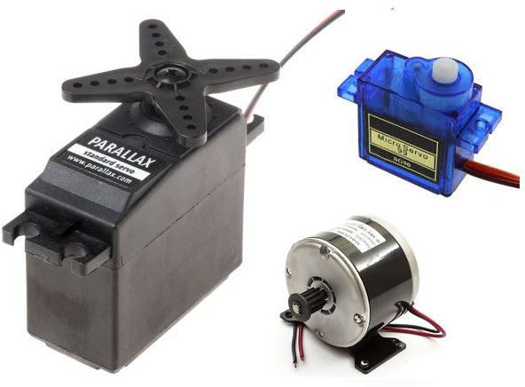
Not every servo motor can move heavy loads. It depends on your specifications and details. Typically, toy servo motors can move loads from 1 kg to 12 kg. There are two types of servo motors DC and AC. AC servo motors can move even heavier loads as they are used in industrial applications. DC servo motors are best for small projects. In this project I am also using a DC servo motor with stm32 microcontroller.
As you learned, servo motors work with PWM signal. Most DC servo motors require 50 Hz frequency for variable duty cycle operation. Below are the standard requirements waveforms. Our engine also demands the same standard.
As you learned, servo motors work with PWM signal. Most DC servo motors require 50 Hz frequency for variable duty cycle operation. Below are the standard requirements waveforms. Our engine also demands the same standard.
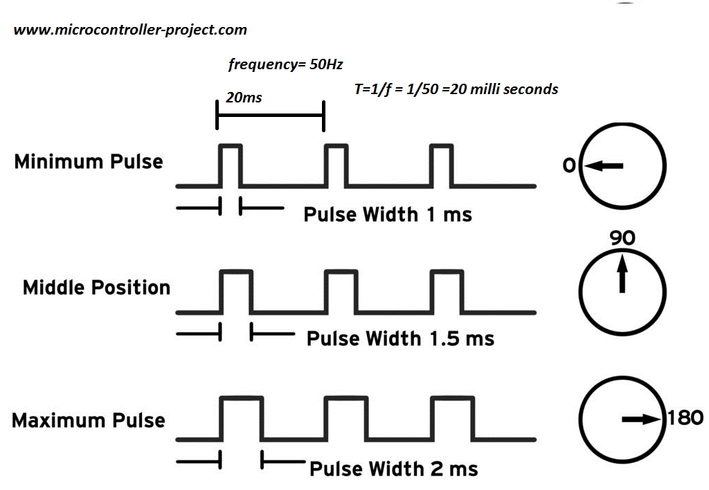
In the period of 20 milliseconds and 2 milliseconds duty cycle, the servo motor arm moves to 180 degrees. In the 1.5 millisecond duty cycle, the arm moves to 90 degrees and in the 1 millisecond duty cycle, the arm rotates to 0 degrees.
Servo with stm32 microcontroller
I will interface the servo with the stm32f103c8t6 microcontroller. I bought a cheap pre-assembled board that mounts the microcontroller on it. To rotate the servo motor arm, three microcontroller pins are used as input. To output the pwm signal, a pin is used. Pin 0,1 and 2 of port A are used as inputs and pin 6 of port B is used to output the pwm signal.
The Stm32f103 microcontroller runs at 3.3 volts while the tower pro sg90 servo motor runs at 5 volts. Therefore, both the module motor and the microcontroller must be powered by different power sources. We cannot drive the servo directly with the stm32 output pwm signal because it is in 3.3V waveform and the motor requires 5V. I inserted a circuit between the two modules to convert 3.3v to 5v. The first transistor is converting the input signal to 5V output, but the signal is inverted. Another transistor inverts the inverted signal and brings it back to the original logic. So now 3.3V at the input cross ponds to 5V at the output of the servo motor.
The Stm32f103 microcontroller runs at 3.3 volts while the tower pro sg90 servo motor runs at 5 volts. Therefore, both the module motor and the microcontroller must be powered by different power sources. We cannot drive the servo directly with the stm32 output pwm signal because it is in 3.3V waveform and the motor requires 5V. I inserted a circuit between the two modules to convert 3.3v to 5v. The first transistor is converting the input signal to 5V output, but the signal is inverted. Another transistor inverts the inverted signal and brings it back to the original logic. So now 3.3V at the input cross ponds to 5V at the output of the servo motor.
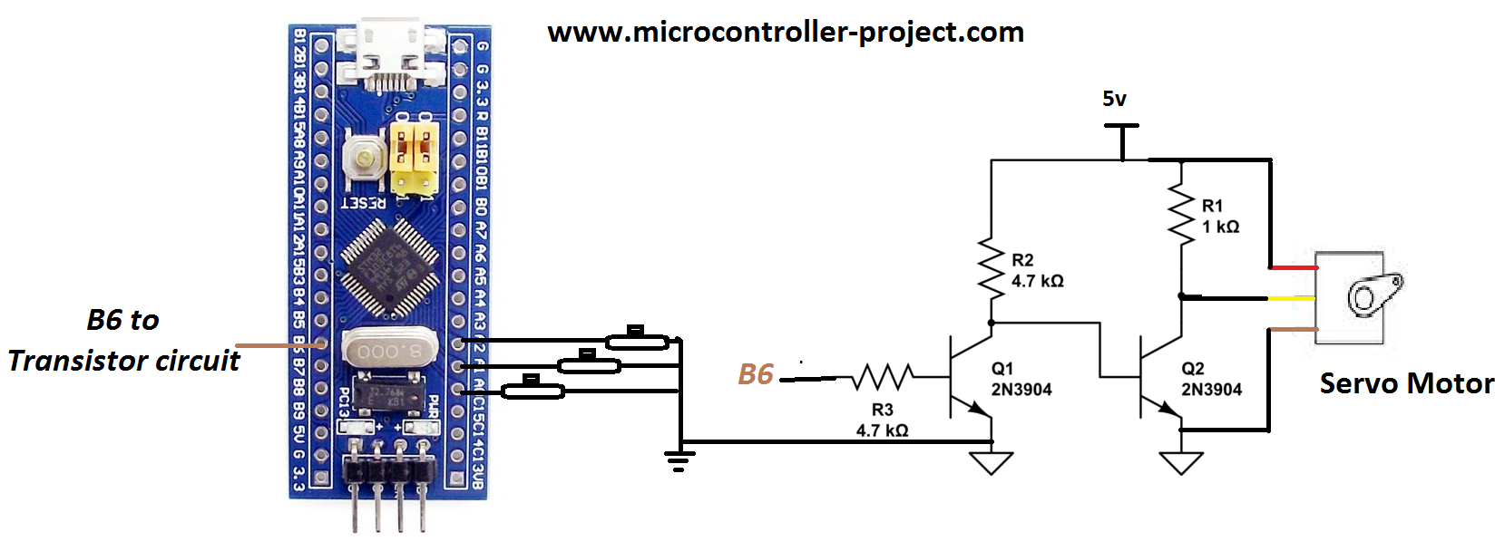
Servo motor controlled with Stm32f103 microcontroller
In the above circuit, make sure to connect the motor and microcontroller power supply grounds. You can also use the ULN2003 IC here instead of the two transistors. ULN2003 contains the same circuit with flying diodes.
In stm32cubemx initialize 3 pins Port-A pins 1,2 and 3 as input. If you don't know how to do this, I have a simple tutorial for you.
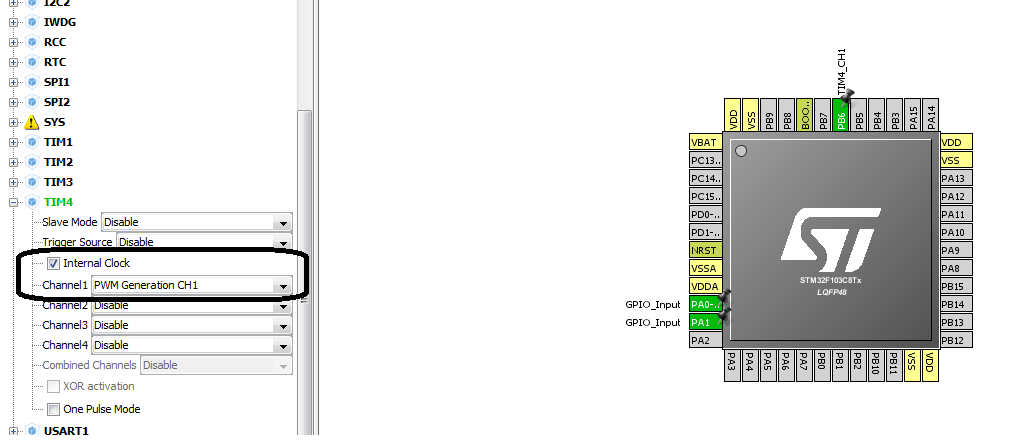
I will output the pwm signal on PB6. For this you have to make some settings in the stm32cubemx ide. How to select the channel and configure some other things. Before proceeding, I would like you to make a simple tutorial on pwm pin selection and duty cycle calculation formula.
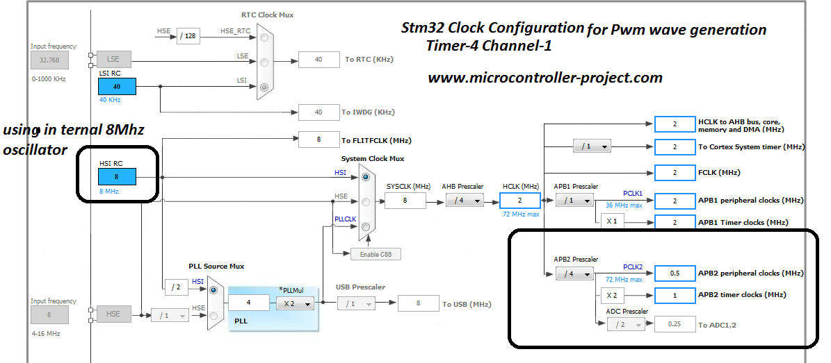
The above tutorial is very important to understand the code flow and settings below. STM32 microcontroller internal oscillator is used in the project. Although the card has an external 8 MHz oscillator, I preferred to use the internal one. The final clock of timer 4 is 1 MHz.
I then calculated the counter register values and other values needed for input into the timer-4 configuration. You can see the formula and other value calculations in the tutorial above.
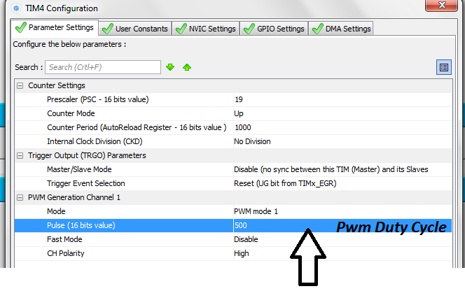
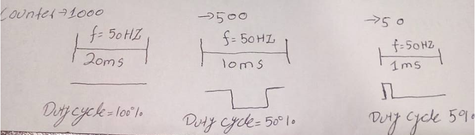
My counter period is 1000. This means at 1000 the pwm duty cycle will be 100% with period of 20 milliseconds or frequency of 50 Hz. At 500 pwm the duty cycle will be 50% which translates to 10 milliseconds. At 5% it will be 1 millisecond and at 10% it will be 2 milliseconds and at 7.5% it will be 1.5 milliseconds.
This counter value is used in the code to move the servo motor arm. Below is the code. When button 3 is pressed, the motor moves 180 degrees. When button 2 is pressed, the button rotates 90 degrees and when button 1 is pressed, it returns to 0 degrees.
Internal pull up resistors of Port-A pins Pins #1,2 and 3 are activated. Consequently, only the buttons are connected directly to ground.
Download the project code. The code is written in Keil Uvision 5 IDE. Stm32cubemx is used for microcontroller configuration. The Code folder contains all the keil and stm32cubemx files. The code is open source, you can modify and use it according to your needs. Please provide us with your feedback on the project.


