REQUIREMENTS:
1. Encoder/Decoder (HT12E/HT12D)
Figure 1:
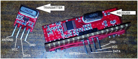
Image of 433 MHz RF transmitter and receiver modules

Figure 2: Prototypes of 433 MHz RF transmitter and receiver modules based on HT12E and HT12D ICs
ABOUT Encoder/Decoder:
Encoders and decoders are used when we need to send our data serially. The pair of encoders and decoders I used are HT12E/HT12D respectively. These are 18-pin ICs. These encoders/decoders require 12 bits for communication, of which 8 are address pins and the remaining four are data pins. For a pair of these encoders/decoders to work together, their addresses must match, only then will the data be decoded on the decoder part. The figure below represents how the wave is generated for communication to occur: Now here the first 8 (1-8) pulses correspond to the address pins and the 9-12 pulses are the data pins. Since there are only 4 bits for data communication, this makes it a 4-bit data encoder/decoder IC. These encoders/decoders also require a clock pulse on pins 15 and 16, which can be provided by simply connecting these two pins through a specified resistance. I used 1M Ohm for the encoder part while the decoder works with 33K Ohm (these values are specified in its datasheet). To learn more about these ICs visit the links below:(CODER):
(DECODER):
ABOUT RF module:
These modules are really simple to deal with. They only require a VCC (+5V), GND (0V) and DATA connection. Some of them also need ANTENNA (ANT) connection. The module I used works at 433 MHz frequency to transmit data wirelessly. Now the question arises is how to interface Rx/Tx with our Decoder/Encoder part. It's very simple; Simply connect the encoder's data output pin with the Tx data pin and the Rx data pin with the decoder's data pin.Circuit diagrams
| Circuit Diagram-433 MHz RF Transmitter-Receiver Modules | 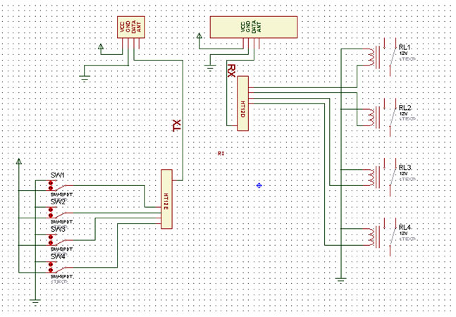 |