This is the most amazing and commercially viable project in which the webcam connected to your computer will move in four directions, top to bottom and left to right, with the help of your fingertips.
The software written in VC++ will control two different AC motors with the help of your computer mouse. The back and forth movement of these motors will move the webcam up and down or left to right, depending on your choice. There are two modes to move the camera in four directions. 1) Automatic and (2) manual. In automatic mode, the camera moves left to right, up and down in a user program sequence, while in manual mode it moves depending on the user's command.
General description:-
There are three basic parts of the project. (1) mechanical (2) hardware and (3) software.
The mechanical part is the camera unit which consists of the camera lens, two AC motors with certain specifications and internal mechanism to rotate the lens. Engine specifications are
Motor type: – Reversible AC motor
Maximum applied voltage: – 230 VAC
Maximum rated RPM: – 5 RPM at 230 VAC
The hardware part is the AC motor drive circuit connected to the LPT port of the PC which will switch the power supplied to the motor and move it accordingly
The software part is the actual interface between the user and the camera which will generate various signals through the LPT and rotate two AC motors.
Note:- Mechanical part is ready and available in the market so we will not discuss this in depth
Hardware and software
Hardware Section: –
The circuit is designed to rotate both AC motors in either direction. For each motor we have two relays, one to turn the motor on or off and the second to change direction. Therefore, four switching relays (C/O) are connected to LPT pins D0-D3 through the ULN2003A current driver chip. All relays are 12 VDC, 300 ohm (sugar cube type, PCB mount). One of the coil terminals of all relays is shorted and connected to the 12 V supply. The second terminal is connected to the output of the ULN chip. The relay contacts (C, NC, NO) are connected as shown in the figure in Circuit Diagram, Guide 1.
Here relays RL1 and RL3 are for switching on/off the motors and RL2 and RL4 are for changing direction. ACM1 is used to move the camera left and right while ACM2 moves the camera up and down. Therefore, by switching these relays, the camera will move in all four directions. The table below will give you an idea of how a software can move the camera using the LPT port
|
Relay(s) |
Data pins |
Camera movement |
Hexadecimal number |
|
RL1 |
D0 |
From left to right |
01h |
|
RL1 and RL2 |
D0-D1 |
Right to left |
03h |
|
RL3 |
D2 |
Upwards |
04h |
|
RL3 and RL4 |
D2-D3 |
From top to bottom |
0Ch |
Software Section: –

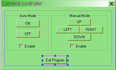
As illustrated first, there are two automatic and manual modes, therefore, in automatic mode the software moves the camera in a pre-programmed sequence and in manual mode the user (operator) can move the camera from the keyboard or mouse. The application window looks like this.
There are two group boxes, seven buttons and two check boxes. Here are the settings
|
Item |
Property |
Context |
|
Group box 1 |
I WENT |
IDC_AUTO |
|
Group box 2 |
I WENT |
IDC_MAN |
|
Button 1 |
I WENT |
IDC_UP |
|
Heading |
ABOVE |
|
|
Button 2 |
I WENT |
IDC_DWN |
|
Heading |
BELOW |
|
|
Button 3 |
I WENT |
IDC_LEFT |
|
Heading |
LEFT |
|
|
Button 4 |
I WENT |
IDC_RGHT |
|
Heading |
RIGHT |
|
|
Button 5 |
I WENT |
IDC_XIT |
|
Heading |
EXIT |
|
|
Button 6 |
I WENT |
IDC_ON |
|
Heading |
ABOUT |
|
|
Button 7 |
I WENT |
IDC_OFF |
|
Heading |
OFF |
|
|
Checkbox 1 |
I WENT |
IDC_CHECK1 |
|
Heading |
Enable |
|
|
Checkbox 2 |
I WENT |
IDC_CHECK2 |
|
Heading |
Enable |
After completing the design, we now have to attach the code to these buttons. We have two activation buttons here, so only one mode will be activated at a time. As you activate one mode, the second will be deactivated. In manual mode, all four given buttons will send the hexadecimal number given in the above table to the LPT port address which is 0378 for the specific relay to get energized and rotate the motor.
Automatic mode is a little different. Camera movement is pre-programmed. The camera moves 150 degrees. From left to right and 150 degrees. From top to bottom. Now as the engine is 5 RPM it means it rotates 1800 degrees. In 60 sec. So, in 1 second, the motor rotates 30 degrees. Thus, to complete 150 degrees, it takes 5 seconds.
Now the movement is divided into 6 stages
- From left to right means 5 seconds (01h)
- From right to middle means 2.5 sec (03h)
- From the middle to the top again 2.5 seconds (04h)
- From top to bottom. 5 sec (0Ch)
- From bottom to middle. 2.5 sec (04h)
- From the middle to the left again 2.5 seconds (03h) and this cycle repeats
So, for this we use a counter which will count in 0.5 second intervals. The total cycle time is 20 seconds, which means the counter counts up to 40. The program assumes that when automatic mode is activated, the cameras are in the leftmost position
Circuit diagrams
| webcam-1 |  |

