The figure above shows a diagram of the system. The azimuth motor (AZ motor) and elevation motor (EL motor) are shown. Sensors are attached to the antenna shafts as the satellite dish changes position, the sensor's analog output changes.
As soon as the sensor position matches the entered position in terms of azimuth angle and elevation angle, both motors stop rotating. Subsequently, if there is any deviation in the position of the antenna due to any circumstance, it automatically reaches the desired position using motors. If we want to change the position of the antenna (perhaps to track another satellite), then we change the azimuth angle and elevation angle and again the antenna moves to a new modified position.
This is the description of the real system. It is composed of large and heavy motors that can bear the load, and the size of the rotating satellite dish varies from 3 to 15 meters. The RVDT is chosen (or even customized) according to the desired degree of rotation of the antenna. It provides corresponding analog voltage output according to the antenna position changes. The entire system is precisely calibrated for RVDT output according to the antenna angle position in both dimensions.
For example, consider that the RVDT has an angular range of -45o to +45o, and the corresponding analog output is 0 to 5V. This means that for an angle change of 90o, the voltage change range is 5V . Therefore, for every degree of change in angle, the output voltage changes by 5/90 = 0.055 = 55 mV (approx.). If this RVDT is used in a system such that as the antenna moves from 0o to 90o it provides a 0 to 5V output, then each degree change in antenna position is detected as a change of degree. ± 55 mV at voltage output. The control system detects this voltage and generates signals to activate the motors. The motors and corresponding gear mechanism are also designed to rotate the antenna in the range of 0o to 90o (or 180o or even more) in increments of 1o in both dimensions. Generally, the elevation angle range is 0o to 90o, and the azimuth angle range can be 0o to 180o or even 360o.
This is how the real system is designed and works. But here I discussed the demonstration of such a system.
Demo Model: –
The figure shows the layout of the system. There are two engines. Both motors are 12V DC gearmotors with a speed of 10 RPM. The motor that rotates the dish in the horizontal plane is known as the azimuth motor, and another motor rotates it in the vertical plane which is the elevation motor. Two opto-switch sensors are used to provide feedback of the engine's angular position. It uses a coding wheel that is fixed to the shaft of each motor. The coding wheel has holes (grooves) at 10o, 20o, 30o, in the same way. The arrangement is made in such a way that as the engine rotates, the wheel also rotates; its holes pass through the sensor opening and generate a pulse. This means that the sensor generates a pulse every 10o engine rotation. The figure itself describes how the entire arrangement is done, but let me discuss it step by step.
• The entire system is mounted on a wooden box that houses the circuit and serves as a base or platform for the entire mechanism.
• The 1st DC motor (azimuthal motor) is fixed inside a wooden box using screws and bolts. The coding wheel (azimuth wheel) is fixed with its axis as shown
• Sensor 1 MOC7811 (azimuth sensor) is also mounted vertically using a small wooden bracket on the same wooden platform so that the azimuth coding wheel holes pass through the sensor opening
• An AU-shaped metal strip about 2 inches wide is welded directly to the DC motor shaft. one side of the U shape is quite long to the others, as shown.
• This strip is used to mount the 2nd DC motor and another sensor. The 2nd DC motor (lift motor) is mounted on the U-strap using mounting clamp and screws on the short side, while sensor 2 (lift sensor) is fixed on the end of the long arm (side)
 • A plate (made of cardboard and aluminum foil) is fixed directly on the shaft of this motor 2. The 2nd coding wheel (lifting wheel) is also fixed on the shaft end of motor 2 as shown
• This wheel and elevation sensor are again fixed so that the holes in the wheel pass through the sensor opening
Here is the snap of the model.
• A plate (made of cardboard and aluminum foil) is fixed directly on the shaft of this motor 2. The 2nd coding wheel (lifting wheel) is also fixed on the shaft end of motor 2 as shown
• This wheel and elevation sensor are again fixed so that the holes in the wheel pass through the sensor opening
Here is the snap of the model.
 Demo model working: –
• Initially, the angle of both motors is set at 0o on the coding wheel. It means that the satellite dish has an azimuth angle of 0o and an elevation angle of 0o
• The azimuth angle can be set from 0o to 350o in 10o increments. User can set desired angle using buttons
• Next, the user must define an elevation angle. Can be adjusted from 0o to 70o in 10o step using buttons
• When both angles are set, the user presses another button to rotate the dish
• As the button is pressed, the azimuth motor begins to rotate to set the azimuth angle. As the motor rotates, the coding wheel also rotates and its holes pass through the sensor opening. The sensor generates pulses that provide feedback on the angular position of the motor. The motor rotates until the set angle and the actual motor rotation angle become equal. If the set angle is greater than the actual motor angle, the motor rotates clockwise and if the set angle is smaller, the motor rotates counterclockwise
• The next lift motor starts to rotate. It rotates the platter and also the second coding wheel. Again the motor rotates until the set angle and the actual rotation angle of the motor become equal. It also rotates CW or CCW depending on whether the set angle is greater or less than the actual angle
• Thus, the satellite dish reaches the desired angular position in the azimuth and elevation planes
Hardware
As shown in the figure, the circuit is built using MOC7811 sensors, L293D motor driver chip, 20×4 LCD and ATMega16 microcontroller.
• The sensor circuits are built around the MOC7811. Both sensor circuits are identical. The internal IR LED receives 5V power through a 33.0E current limiting resistor, and the phototransistor is connected in switch configuration using an external 1K resistor. The final output of the sensor circuit is through the phototransistor collector
• Both sensor outputs are connected to the external interrupt pins PD2 and PD3 of the ATMega16.
• PORTA pins PA0 to PA4 are connected to ground through a resistor network (5 1K resistors). Five buttons are connected to these pins such that when the button is pressed, logic 1 is given as input. The rest of the PORTA pins are connected with Vcc
• PORTC drives LCD data pins D0 – D7. Two control pins Rs and En or LCD are connected to PORTB pins PB4 and PB5 respectively. LCD RW pin is connected to ground to allow recording
• PORTB pins PB0 – PB3 drive 2 DC motors through the L293D chip. These pins are connected to the input of the L293D, and two motors are connected to the outputs of the L293D
• A 16 MHz crystal is connected to the crystal input pins of the ATMega16. Two 22pf capacitors are connected for polarization and crystal stability
• Reset button connected as shown with the reset input pin to provide a manual reset to the microcontroller
Operation: –
• Initially the LCD shows the AZ angle set and the EL angle set to 0o. It also shows the current AZ angle and EL angle as 0o.
• User should set the AZ angle and EL angle by pressing the AZ angle increase/decrease buttons and the EL angle increase/decrease buttons
• Every time a button is pressed, the angle changes by 10o
• After setting the rotation angles, the platter button is pressed. Both motors rotate one by one until the satellite dish angles match the set azimuth angle and elevation angle
Software
• The software is written in C language
• Compiled using AVR Studio 4
• Tested using AVR simulatro1 for ATmega16 device (available with AVR Studio 4)
Demo model working: –
• Initially, the angle of both motors is set at 0o on the coding wheel. It means that the satellite dish has an azimuth angle of 0o and an elevation angle of 0o
• The azimuth angle can be set from 0o to 350o in 10o increments. User can set desired angle using buttons
• Next, the user must define an elevation angle. Can be adjusted from 0o to 70o in 10o step using buttons
• When both angles are set, the user presses another button to rotate the dish
• As the button is pressed, the azimuth motor begins to rotate to set the azimuth angle. As the motor rotates, the coding wheel also rotates and its holes pass through the sensor opening. The sensor generates pulses that provide feedback on the angular position of the motor. The motor rotates until the set angle and the actual motor rotation angle become equal. If the set angle is greater than the actual motor angle, the motor rotates clockwise and if the set angle is smaller, the motor rotates counterclockwise
• The next lift motor starts to rotate. It rotates the platter and also the second coding wheel. Again the motor rotates until the set angle and the actual rotation angle of the motor become equal. It also rotates CW or CCW depending on whether the set angle is greater or less than the actual angle
• Thus, the satellite dish reaches the desired angular position in the azimuth and elevation planes
Hardware
As shown in the figure, the circuit is built using MOC7811 sensors, L293D motor driver chip, 20×4 LCD and ATMega16 microcontroller.
• The sensor circuits are built around the MOC7811. Both sensor circuits are identical. The internal IR LED receives 5V power through a 33.0E current limiting resistor, and the phototransistor is connected in switch configuration using an external 1K resistor. The final output of the sensor circuit is through the phototransistor collector
• Both sensor outputs are connected to the external interrupt pins PD2 and PD3 of the ATMega16.
• PORTA pins PA0 to PA4 are connected to ground through a resistor network (5 1K resistors). Five buttons are connected to these pins such that when the button is pressed, logic 1 is given as input. The rest of the PORTA pins are connected with Vcc
• PORTC drives LCD data pins D0 – D7. Two control pins Rs and En or LCD are connected to PORTB pins PB4 and PB5 respectively. LCD RW pin is connected to ground to allow recording
• PORTB pins PB0 – PB3 drive 2 DC motors through the L293D chip. These pins are connected to the input of the L293D, and two motors are connected to the outputs of the L293D
• A 16 MHz crystal is connected to the crystal input pins of the ATMega16. Two 22pf capacitors are connected for polarization and crystal stability
• Reset button connected as shown with the reset input pin to provide a manual reset to the microcontroller
Operation: –
• Initially the LCD shows the AZ angle set and the EL angle set to 0o. It also shows the current AZ angle and EL angle as 0o.
• User should set the AZ angle and EL angle by pressing the AZ angle increase/decrease buttons and the EL angle increase/decrease buttons
• Every time a button is pressed, the angle changes by 10o
• After setting the rotation angles, the platter button is pressed. Both motors rotate one by one until the satellite dish angles match the set azimuth angle and elevation angle
Software
• The software is written in C language
• Compiled using AVR Studio 4
• Tested using AVR simulatro1 for ATmega16 device (available with AVR Studio 4)
Project source code
###
//Program to Here is the complete program with necessary comments. #include#include #include #include unsigned int set_az_angle=0, set_el_angle=0,dish_az_angle=0,dish_el_angle=0, rotate_reverse_flag=0,up_down_flag=0; ///////////////// function to send data to be displayed on LCD ///////////////////// void lcd_senddata(unsigned char data) { _delay_ms(2); PORTB=(1< // get the length of string for(i=0;i // write every char one by one s++; } } ////////////// function to initialize LCD //////////////////////////////// ////////// void lcd_init { lcd_sendcmd(0x3E); // 8 bits per char lcd_sendcmd(0x0E); // screen on and cursor ON lcd_sendcmd(0x01); // clear LCD memory and home cursor lcd_sendcmd(0x84); // go to column 4 of line 1 lcd_printstr("Dish antenna"); // display message lcd_sendcmd(0xC4); // go to column 4 of line 2 lcd_printstr("angle control"); } ////////////////// function to display angle value on LCD ///////////////////////// // void display_value(unsigned int angle) { unsigned int t1,a; unsigned char asci(3); unsigned int t; t = angle; if(t>=100) { a=2; while(t>=10) { t1=t%10; asci(a)=t1+0x30; t=t/10; The--; } asci(0)=t+0x30; } else { t1=t%10; asci(2)=t1+0x30; t=t/10; asci(1)=t+0x30; asci(0)=0x20; } lcd_senddata(asci(0)); lcd_senddata(asci(1)); lcd_senddata(asci(2)); lcd_senddata(0xDF); } /////////////////////// function to increment azimuth angle value ///////////////////// void inc_az_angle { if(set_az_angle<360) set_az_angle+=10; // increment set angle by 10o till its not 360o lcd_sendcmd(0x8D); display_value(set_az_angle); } /////////////////////// function to decrement azimuth angle value //////////////////// void dec_az_angle { if(set_az_angle>0) set_az_angle-=10; // decrement set angle by 10o till its not 0o lcd_sendcmd(0x8D); display_value(set_az_angle); // display it on LCD } /////////////////////// function to increment elevation angle value ////////////////// void inc_el_angle { if(set_el_angle<70) set_el_angle+=10; lcd_sendcmd(0xCD); display_value(set_el_angle); } /////////////////////// function to decrement elevation angle value ////////////////// void dec_el_angle { if(set_el_angle>0) set_el_angle-=10; lcd_sendcmd(0xCD); display_value(set_el_angle); } //////////////// function to rotate dish ////////////////////////////// /////// void rotate_dish { if(set_az_angle>dish_az_angle) // new set az angle is larger rotate_reverse_flag=0; // rotate dish CW else // otherwise rotate_reverse_flag=1; // rotate dish CCW if(set_el_angle>dish_el_angle) // if new set el angle is larger up_down_flag=0; // move dish up else // otherwise up_down_flag=1; // move dish down if(rotate_reverse_flag==0) { //////// rotate CW dish till set az angle and dish az angle are not the same while(set_az_angle!=dish_az_angle) PORTB = 0x01; PORTB = 0x00; // stop when same } else { // rotate CCW dish till set az angle and dish az angle are not the same while(set_az_angle!=dish_az_angle) PORTB = 0x02; PORTB = 0x00; // stop when same } if(up_down_flag==0) { // move dish up till set el angle and dish el angle are not the same while(set_el_angle!=dish_el_angle) PORTB = 0x04; PORTB = 0x00; // stop when same } else { // move dish down till sent el angle and dish el angle are not the same while(set_el_angle!=dish_el_angle) PORTB = 0x08; PORTB = 0x00; // stop when same } } int main(void) { DDRC=0xFF; // initialize ports as DDRD=0xC3; // input or output DDRB=0xFF; DDRA=0x00; PORTC=0x00; PORTB=0x00; MCUCR = (1< GICR=(1< // enable external interrupts know ; // enable global interrupts lcd_init; // initialize LCD _delay_ms(2000); // wait for 2 sec lcd_sendcmd(0x01); // clearLCD lcd_printstr("Set AZ angle:"); // display angle values display_value(set_az_angle); lcd_sendcmd(0xC0); lcd_printstr("Set EL angle:"); display_value(set_el_angle); lcd_sendcmd(0x94); lcd_printstr("Dish EL angle:"); display_value(set_el_angle); lcd_sendcmd(0xD4); lcd_printstr("Dish EL angle:"); display_value(set_el_angle); loop:while(PINA==0xE0); // loop until no switch is pressed switch(PINA) { case 0xE1: // when switch 1 is pressed inc_az_angle ; // increment az angle _delay_ms(200); // delay for key debounce break; case 0xE2: // same as above dec_az_angle ; _delay_ms(200); break; case 0xE4: inc_el_angle ; _delay_ms(200); break; case 0xE8: dec_el_angle ; _delay_ms(200); break; case 0xF0: rotate_dish; break; } goto loop; } ///////////////// external interrupt 0 service routine //////////////////////////// // ISR(INT0_vect) { if(rotate_reverse_flag==1) // if dish is rotating reverse { if(dish_az_angle>0) dish_az_angle-=10; // decrease angle value by 10 } else // otherwise { if(dish_az_angle<360) dish_az_angle+=10; // increment angle value by 10 } lcd_sendcmd(0xA2); display_value(dish_az_angle); // display angle value on LCD } ///////////////// external interrupt 1 service routine //////////////////////////// // ISR(INT1_vect) { if(up_down_flag==1) // if dish is moving down { if(dish_el_angle>0) dish_el_angle-=10; // decrease angle value by 10 } else // otherwise { if(dish_el_angle<70) dish_el_angle+=10; // increment it by 10 } lcd_sendcmd(0xE2); display_value(dish_el_angle); // display it on LCD } ###
Circuit diagrams
| main circuit | 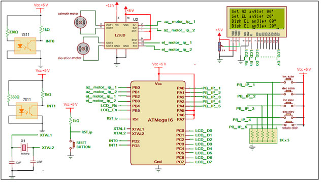 |