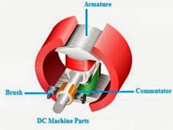
The voltage produced in the coil (armature) of a DC generator is generally alternating current. Commutation in a DC machine or more precisely commutation in a DC generator is the process of converting the AC armature coil windings generated from a DC machine into DC current by touching the commutator and stationary brushes.
In the case of a DC motor, the input direct current must be regenerated alternately in the armature, which in the case of a DC motor is also done by commutation.
-
Separately excited generator
This conversion of current from the rotating coil of a DC machine to the stationary brushes must maintain constantly moving contacts between the commutator segment and the brush. When the armature starts rotating, the coils rotate under a pole (N-pole) between a positive and negative brush, causing the electrical current flowing through this coil to flow in a very short direction within the commutator segment. Now the coil is short-circuited using a brush for a very short fraction of time (1/500th of a second). This is called the switching period. During this short-circuit period, the armature coil rotates under the S pole and rotates between a negative brush and the positive brush that follows it. Now the direction is reversed, i.e. within the opposite direction to the commutator segments. This development of current reversal is called the switching method. We get power from the brush terminals.
Switching is considered optimal when the switching or current reversal process is completed at the end of the short circuit time or switching interval. When the current reversal is completed during the tangential time, sparks occur at the brush contacts and the commutator surface is damaged due to heating and the machine is said to be poorly commutated.

-
Classification of DC machines
Switching in DC machines
For the purpose of the switching method, we consider a DC machine with an armature surrounded by a ring winding. Let us additionally consider that the width of the switched rod is equal to the width of the brush and the current flowing through the conductor is I. C.
The brush can move from right to left while the commutator moves from left to right.
In the initial position, the brushes are connected to the commutator bar B, as shown in Fig. a. Then the total current conducted to the brush from commutator bar B is 2I C.
-
Classification of DC machines
If the anchor starts moving to the right before the brush contacts rod A. Then the armature current flows through 2 paths and through rods A and B (as shown in Fig. B). The total current (2I C ) remains trapped by the brush.
As the contact space of rod A with the brush increases and the contact space of rod B decreases, the current flow through the rod increases and decreases at the same time. Since the contact space is the same for all commutator bars, the same current flows through all bars (as shown in Fig. C).
When the contact gap between the brush and rod B becomes smaller, the current through coil B changes direction and begins to flow counterclockwise (see Fig. d).
-
Armature reaction in DC machine
If the brush passes completely under bar A (see Fig. e) and is cut off at bar B, current IC flows counterclockwise through coil B and the short circuit is canceled. This method completes the current reversal or switching process.


