The invention of radio revolutionized the world. It was a successful tool for communicating information via wireless communication. Another great invention was the telephone. Do you remember those days when we used those bulky landlines? Now the era has changed. Landlines are being replaced by cell phones.
We have to accept the fact that wireless communication has become an essential part of our life. If we look around us, we will find many devices that work on wireless communication such as mouse, keyboard, lock keys, radio, cordless phone and many more. Additionally, wireless communication is sometimes called radio frequency (RF) communication.
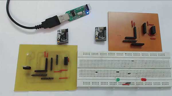
Fig. 1: Prototype wireless communication device based on NRF24LE1
Why are we passionate about wireless communication? The answers are obvious. First, we want to get rid of the wires that are around us and cause us irritation. Secondly, we want remote access to information. These are the reasons that have increased the demand for wireless communication. The time is not far when wired communication will become obsolete.
This article is dedicated to establishing wireless communication between two NRF modules. We'll start with the basic code for transmitting an 8-bit value wirelessly.
Let's review some specifications about the RF transceiver used in the NRF24LE1.
Firstly, it works on the 2.4 GHz frequency, which is in the ISM band that is free to use for industrial, scientific and medical purposes. Additionally, it uses GMSK modulation.
Secondly, NRF works at data rates of 250 Kbps, 1Mbps or 2Mbps. Additionally, the NRF24LE1 is fully compatible with other NRF24LXX series. We will be using nrfsdk (software development kit) provided by Nordic Semiconductors Ltd.
Note: Refer to our previous articles on this module for more understanding.
We will now discuss some built-in functions provided by nrfsdk:
• hal_nrf_set_operation_mode – This function is used to select TX or RX mode
• hal_nrf_set_rx_payload_width – To set the width of the payload to be received
• hal_nrf_set_power_mode – This function is used to turn on the RF.
• hal_nrf_write_tx_payload – This function receives payload data to be transmitted.
• CE_PULSE – This function starts transmission
• CE_HIGH – To enable the receiver
• hal_nrf_get_clear_irq_flags : This function reads and clears radio-related interrupt flags.
• hal_nrf_rx_fifo_empty : To check whether the Rx buffer is empty or not.
• hal_nrf_flush_tx : To flush the Tx FIFO buffer
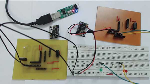
Fig. 2: Image of NRF24LE1 based wireless communication device
The description of various functions is:
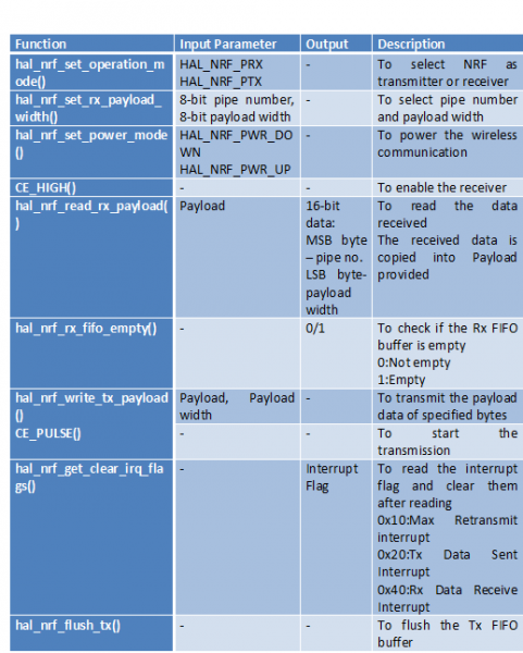
Fig. 3: Table listing various functions of the NRF24LE1
These functions were used in the code. The code is commented for greater understanding. Please share your feedback in the comments section below.
Project source code
###
//Program to //Program to Rx /* Copyright (c) 2009 Nordic Semiconductor. All Rights Reserved. * *The information contained herein is confidential property of Nordic * Semiconductor ASA.Terms and conditions of usage are described in detail * in NORDIC SEMICONDUCTOR STANDARD SOFTWARE LICENSE AGREEMENT. * * Licensees are granted free, non-transferable use of the information. AT THE * WARRENTY of ANY KIND is provided. This heading must NOT be removed from * the file. * * $LastChangedRevision: 2211 $ */ /** @filet * @brief Enhanced ShockBurst Primary Receiver example * @defgroup esb_prx_example Enhanced ShockBurst Primary Receiver (PRX) example * @{ * @ingroup nrf_examples * * @brief This example monitors for data and writes the first byte (byte 0) of the * received payloads to P0. * * The example shows the minimum required setup for receiving packets from a * primary transmitter (PTX) device. * * The following default radio parameters are being used: * - RF channel 2 * - 2 Mbps data rate * - RX address 0xE7E7E7E7E7 (pipe 0) and 0xC2C2C2C2C2 (pipe 1) * - 1 byte CRC * * The project @ref esb_ptx_example can be used as a counterpart for transmitting the data. * */ #include "nrf24le1.h" // I/O header file for NRF24LE1 #include "hal_clk.h" // library containing clock functions #include// standard integers library #include "hal_nrf.h" // library containing wireless communication functions // Global variables uint8_t payload(3); // payload to be received // main function void main { #ifdef MCU_NRF24LE1 while(hal_clk_get_16m_source != HAL_CLK_XOSC16M) { // Wait until 16 MHz crystal oscillator is running } #endif #ifdef MCU_NRF24LU1P // Enable radio SPI RFCTL = 0x10; #endif // Set P0 as output P0DIR = 0; // Enable the radio clock RFCKEN = 1; // Enable RF interrupt RF = 1; // Enable global interrupt EA = 1; // Configure radio as primary receiver (PTX) hal_nrf_set_operation_mode(HAL_NRF_PRX); // Set payload width to 3 bytes hal_nrf_set_rx_payload_width((int)HAL_NRF_PIPE0, 3); // Power up radio hal_nrf_set_power_mode(HAL_NRF_PWR_UP); // Enable receiver CE_HIGH ; // infinite loop for(;;){} } // Radio interrupt NRF_ISR { uint8_t irq_flags; // Read and clear IRQ flags from radio irq_flags = hal_nrf_get_clear_irq_flags ; // If data received if((irq_flags & (1<<(uint8_t)HAL_NRF_RX_DR)) > 0) { // Read payload while(!hal_nrf_rx_fifo_empty ) { hal_nrf_read_rx_payload(payload); } // Write received payload(0) to port 0 P0 = payload(0); } } /** @} */ //Program to Tx /* Copyright (c) 2009 Nordic Semiconductor. All Rights Reserved. * *The information contained herein is property of Nordic Semiconductor ASA. * Terms and conditions of usage are described in detail in NORDIC * SEMICONDUCTOR STANDARD SOFTWARE LICENSE AGREEMENT. * * Licensees are granted free, non-transferable use of the information. AT THE * WARRENTY of ANY KIND is provided. This heading must NOT be removed from * the file. * * $LastChangedRevision: 2513 $ */ /** @filet * @brief Enhanced ShockBurst Primary Transmitter example * @defgroup esb_ptx_example Enhanced ShockBurst Primary Transmitter (PTX) example * @{ * @ingroup nrf_examples * * @brief This example sends packets continuously. The contents of P0 are * sent in the first payload byte (byte 0). * * The example shows the minimum required setup for transmitting packets to a * primary receiver (PRX) device. * * The following default radio parameters are being used: * - RF channel 2 * - 2 Mbps data rate * - TX address 0xE7E7E7E7E7 * - 1 byte CRC * * The project @ref esb_prx_example can be used as a counterpart for receiving the data. * */ #include "nrf24le1.h" // I/O header file for NRF24LE1 #include "hal_clk.h" // library containing clock functions #include // standard integers library #include "hal_nrf.h" // library containing wireless communication functions #include // standard boolean library // Global variables static bool volatile radio_busy; // main function void main(void) { uint8_t payload(3); // payload to be transmitted #ifdef MCU_NRF24LE1 while(hal_clk_get_16m_source != HAL_CLK_XOSC16M) { // Wait until 16 MHz crystal oscillator is running } #endif #ifdef MCU_NRF24LU1P // Enable radio SPI RFCTL = 0x10U; #endif // Enable the radio clock RFCKEN = 1U; // Enable RF interrupt RF = 1U; // Enable global interrupt EA = 1U; // Power up radio hal_nrf_set_power_mode(HAL_NRF_PWR_UP); // infinite loop for(;;) { // Put P0 contents in payload(0) payload(0) = ~P0; // write compliment of Port0 // Write payload to radio TX FIFO hal_nrf_write_tx_payload(payload, 3U); // Toggle radio CE signal to start transmission CE_PULSE ; radio_busy = true; // Wait for radio operation to finish while (radio_busy) { } } } // Radio interrupt NRF_ISR { uint8_t irq_flags; // Read and clear IRQ flags from radio irq_flags = hal_nrf_get_clear_irq_flags ; switch(irq_flags) { // Transmission success case (1 << (uint8_t)HAL_NRF_TX_DS): radio_busy = false; // Data has been sent break; // Transmission failed (maximum re-transmits) case (1 << (uint8_t)HAL_NRF_MAX_RT): // When a MAX_RT interrupt occurs the TX payload will not be removed from the TX FIFO. // If the packet is to be discarded this must be done manually by flushing the TX FIFO. // Alternatively, CE_PULSE can be called re-starting transmission of the payload. // (Will only be possible after the radio irq flags are cleared) hal_nrf_flush_tx ; radio_busy = false; break; default: break; } } /** @} */ ###
Circuit diagrams
| Circuit Diagram-NRF24LE1-Based Wireless Communication Device | 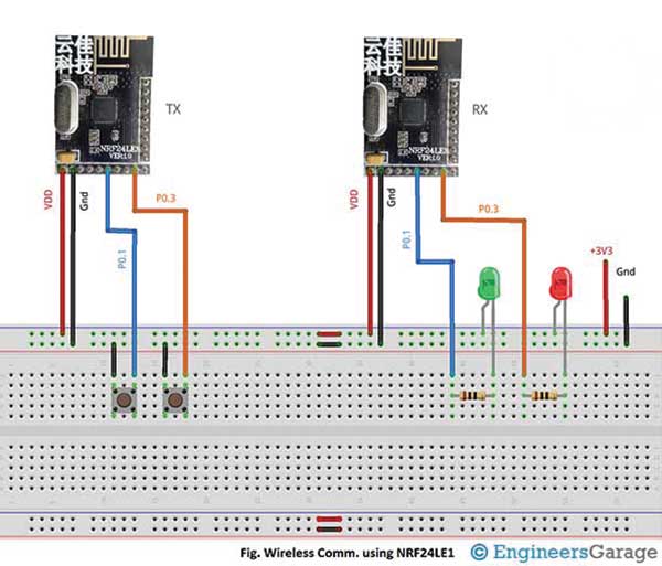 |
Project video