Self-Programming Mode ( SPM ) is a feature that allows a microcontroller to program its own flash memory. Using SPM, a microcontroller can program itself with an SPM code. SPM is commonly used with microcontroller Boot-Loader codes that help to program the microcontroller serially. In the AVR microcontroller, the SPM is only available for code running in the BLS of flash memory. With the help of SPM, a code in BLS can rewrite the application's flash memory entirely or part of it. You can even rewrite your own code in the BLS section.
SPM is a key factor of Boot-Loader code as the main function of Boot-Loader is to load an application code into the flash section of the application. The Boot-Loader can receive binary code from other memory chips, SD cards or through the microcontroller's serial port in case of serial programming. It is then with the help of the SPM that the microcontroller writes the binary code in the flash section of the application.
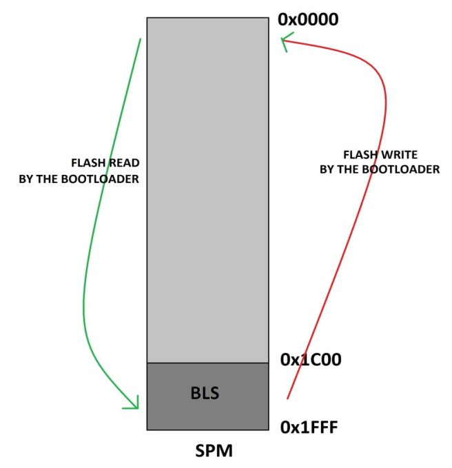
Self-programming mode (SPM) is a feature of the AVR microcontroller that allows the microcontroller to program its own flash memory. Only code running on BLS can make use of this SPM feature. The microcontroller can be made to start execution from the BLS from there the code can access the flash area of the application. The BLS can read or write the contents of all flash, including the BLS itself.

Fig. 2: Block diagram of SPM with BLS on AVR
The task of writing BLS code with SPM has been simplified by the APIs available in the header file
|
FUNCTION |
DESCRIPTION |
PARAMETER |
|
boot_is_spm_interrupt |
Check whether SPM interrupt is enabled. |
|
|
boot_lock_bits_set (lock_bits) |
Set the Boot-Loader lock bits |
A mask of which bootloader lock bits to set |
|
boot_lock_bits_set_safe (lock_bits) |
Waits for EEPROM and SPM operations to complete before setting lock bits |
A mask of which bootloader lock bits to set |
|
boot_lock_fuse_bits_get (address) |
Read the lock or fuse bits at the given address. Returns 0 or 1 depending on whether the fuse bit is programmed or not |
The address to read |
|
boot_page_erase (address) |
Delete the flash page referred to by the address |
A byte address in flash |
|
boot_page_erase_safe (address) |
waits for EEPROM and SPM operations to complete before erasing the page |
A byte address in flash |
|
boot_page_fill (address, data) |
Fill Boot-Loader temporary page buffer for flash address with data word |
The address is a byte address. Data is a word |
|
boot_page_fill_safe (address, data) |
waits for EEPROM and SPM operations to complete before filling the page |
The address is a byte address. Data is a word |
|
boot_page_write (address) |
Write the Boot-Loader temporary page buffer to the flash page containing the address |
Flash byte address |
|
boot_page_write_safe (address) |
waits for EEPROM and SPM operations to complete before writing the page |
Flash byte address |
|
boot_rww_busy |
Check if the RWW section is busy |
|
|
boot_rww_enable |
Enable the Read-While-Write memory section. |
|
|
boot_rww_enable_safe |
waits for EEPROM and SPM operations to complete before activating RWW memory |
|
|
boot_signature_byte_get (address) |
Returns the signature line byte at the given address |
The parameter address can be from 0 to 0x1F |
|
boot_spm_busy |
Check if the SPM instruction is busy |
|
|
boot_spm_busy_wait |
Wait while SPM instruction is busy |
|
|
boot_spm_interrupt_disable |
Disable SPM interrupt |
|
|
boot_spm_interrupt_enable |
Enable SPM interrupt |
|
Figure 3: Important APIs in the AVR header file for SPM
Using the above APIs, one can write code for SPM on an AVR microcontroller, as long as the code follows certain steps in order. In this project, the code that was programmed from the beginning of the flash memory is reprogrammed into another region of the flash memory as such. The task of programming one region of flash memory with the binary obtained from the other region can be accomplished in the following three main steps.
Step: 1 Delete the flash page you are about to write
The first step is to erase the flash page that is about to be written with the new values. The API that helps in executing this step is;
Boot_page_erase (address)
This API can delete an entire page in flash that the parameter addresses. In the code, the address of the erased page is 256. The following image shows the status of the temporary page buffer and flash memory in step 1. The temporary page buffer is a buffer in which an entire page can be stored before it is flashed on a page in flash memory.

Fig. 4: The figure represents the status of the temporary page buffer and flash memory in the AVR SPM
Step:2 Store the values in a temporary buffer before writing to a flash page
This is the second step in which you must store the required binary in a temporary buffer before writing to any flash memory page. The API that can be used for this purpose is;
boot_page_fill (address, data)
This API fills the Boot-Loader's temporary page buffer byte by byte before updating the data in the temporary page buffer into a page as such. The parameter data represents each byte in the buffer and the parameter address represents the page address + offset of the buffer location where the data byte needs to be stored.
The following figure represents the operation in which the temporary page buffer is filled byte by byte using the boot_page_fill(address, data) API.

Fig. 5: Data transfer operation to temporary page buffer using AVR boot_page_fill API
The parameter data in the boot_page_fill API (address, data) is actually read from the first location of the flash memory itself with the help of another API which is available in the header file
pgm_read_byte (address)
|
FUNCTION |
DESCRIPTION |
PARAMETER |
|
pgm_read_byte (address) |
This function returns the byte that reads from the flash memory referred to by the 'address' parameter |
Refers to the flash memory location from which the byte needs to be read |
Step:3 Program the temporary buffer filled into the already erased flash page
This is the final step in which the filled temporary buffer is updated using an API on the already erased page from flash memory. The API that helps in this step is;
boot_page_write (address)

Fig. 6: Temporary buffer data transferred into AVR Flash memory using API
The code in this project that was written for BLS can copy 300 bytes from flash memory to the temporary buffer starting at address 0x0000. These bytes are then transferred to the flash memory page starting at address 0x0100. After doing this, the BLS code will jump to address 0x0100 so that the rewritten binary can be executed next. With this boot loader code, any program we enter at the address starting at 0x0000 will be rewritten to x 0x0100 and executed. A simple blinking LED test application can be written to flash memory starting at 0x0000 to test operation. Update the BLS code first and then the LED application code using the steps explained in the previous project on AVR BLS Blinking LED . When the LED blinks, it means that the code has been rewritten from one section of flash memory to another and is being executed from there.

Fig. 7: LED blinking using SPM of the AVR circuit configured on the breadboard
Project source code
 ###

 #define F_CPU 8000000
###
Project source code
 ###

 #define F_CPU 8000000
###
Circuit diagrams
| Circuit diagram of how to use SPM for Flash to Flash programming |  |
Project Components
- ATmega16
- LCD
- LED
- Resistor


Questions related to this article?
 Ask and discuss on the Electro-Tech-Online.com and EDAboard.com forums.
Tell us what you think!! Cancel reply
You need to be logged in to post a comment.