In any microcontroller, Boot-Loader is the first code executed before the application code. The main function of the Boot-Loader is to load the application code into the microcontroller's flash memory and execute it. In AVR microcontroller Self Programming Mode (SPM) helps the Boot-Loader to load a specific application from where the application binary is stored. The Boot-Loader can receive binary code from other memory chips, SD cards or through the microcontroller's serial port in case of serial programming.
It is then with the help of the SPM that the microcontroller writes the binary code in the flash section of the application.
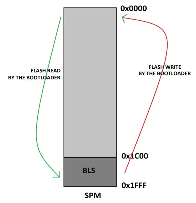
The BLS section is typically used to store the microcontroller bootloader code. Boot-Loader code can be used to initialize the peripherals on the microcontroller, initialize the devices connected to the microcontroller, select the application to load and run from a storage medium, load the selected application to the applications section, jump to the applications section and run the application. Code running in the BLS section can be executed in Self-Programming Mode (SPM) modes that are blocked for code running in the Application section. Using SPM instructions, the BLS code can rewrite the code in the application section or the code in the BLS itself.

Fig. 2: Block diagram of the SPM function with BLS on the AVR
The task of writing BLS code with SPM has been simplified by the APIs available in the header file
|
FUNCTION |
DESCRIPTION |
PARAMETER |
|
boot_page_erase (address) |
Delete the flash page referred to by the address |
A byte address in flash |
|
boot_page_fill (address, data) |
Fill Boot-Loader temporary page buffer for flash address with data word |
The address is a byte address. Data is a word |
|
boot_page_write (address) |
Write the Boot-Loader temporary page buffer to the flash page containing the address |
Flash byte address |
Figure 3: Important APIs for the AVR SPM function
Using the above APIs, one can write code for SPM on an AVR microcontroller, as long as the code follows certain steps in order.
· Step: 1 Delete the flash page you are about to write
{W · Step:2 Store binaries in a temporary buffer before writing to a flash page
{W} · Step:3 Program the temporary buffer filled into the already erased flash page
The above three steps are explained in detail in a previous project article on AVR SPM. In this particular project, the data required to fill the temporary page buffer, as discussed in step: 2, is taken from the AVR microcontroller's integrated EEPROM, where a simple code has already been entered. The internal EEPROM of the AVR microcontroller has a capacity of 512 bytes. It can be easily read and written with the help of APIs available in the header file
|
FUNCTION |
DESCRIPTION |
|
empty eeprom_is_ready (empty) |
Returns 1 if the EEPROM is ready for a new read/write operation, 0 otherwise |
|
void eeprom_read_block (void *dst, const void *src, size_t n ) |
Returns a block of n bytes from EEPROM address src to SRAM dst |
|
uint8_t eeprom_read_byte (const uint8_t *p) |
Returns one byte of the EEPROM address referred to by the p pointer |
|
uint32_t eeprom_read_dword (const uint32_t *p) |
Read a 32-bit double of the EEPROM address referred to by the p pointer |
|
float eeprom_read_float (const float *p) |
Returns a float value from the EEPROM referred to by the pointer p |
|
uint16_t eeprom_read_word (const uint16_t *p) |
Read a 16-bit word from the EEPROM address referenced by the p pointer |
|
void eeprom_update_block (const void *src, void *dst, size_t n) |
Update a block of n bytes to the EEPROM dst address of src |
|
void eeprom_update_byte (uint8_t *p, uint8_t value) |
Update a byte value to the EEPROM address referred to by the p pointer |
|
void eeprom_update_dword (uint32_t *p, uint32_t value) |
Update a 32-bit double-word value to the EEPROM address referred to by the p pointer |
|
void eeprom_update_float (float *p, float value) |
Update a float value to the EEPROM address referred to by the p pointer |
|
void eeprom_update_word (uint16_t *p, uint16_t value) |
Update a word value to the EEPROM address referred to by the p pointer |
|
void eeprom_write_block (const void *src, void *dst, size_t n) |
Write a block of n bytes to the EEPROM dst address of src. |
|
void eeprom_write_byte (uint8_t *p, uint8_t value) |
Write a byte value to the EEPROM address referred to by the p pointer |
|
void eeprom_write_dword (uint32_t *p, uint32_t value) |
Write a 32-bit double-word value to the EEPROM address referred to by the p pointer |
|
void eeprom_write_float (float *p, float value) |
Write a float value to the EEPROM referred to by the p pointer |
|
void eeprom_write_word (uint16_t *p, uint16_t value) |
Write a word value to the EEPROM referenced by the p pointer |
Figure 4: APIs for accessing EEPROM memory
The data to fill the temporary buffer as discussed in step: 2 is read from the AVR microcontroller's onboard EEPROM memory using the library function;
uint8_t eeprom_read_byte (const uint8_t *p)
The above function can return the data byte that is stored in the EEPROM address referred to by the pointer argument. The code is written so that the pointer first points to the 0th location of the EEPROM and then increments the address as it reads each byte for storage in the temporary buffer. Thus, the steps with which the binary code is read from the EEPROM memory and flashed in the flash memory are represented pictorially below;
Step: 1 Delete the flash page you are about to write
The first step is to erase the flash page that is about to be written with the new values. The API that helps in executing this step is;
Boot_page_erase (address)
This API can delete an entire page in flash that the parameter addresses. In the code, the address of the erased page is 256. The following image shows the status of the temporary page buffer and flash memory in step 1. The temporary page buffer is a buffer in which an entire page can be stored before it is flashed on a page in flash memory.

Fig. 5: PageErase block diagram in the SPM function
Step:2 Store the values in a temporary buffer before writing to a flash page
This is the second step in which you must store the required binary in a temporary buffer before writing to any flash memory page. The API that can be used for this purpose is;
boot_page_fill (address, data)
This API fills the Boot-Loader's temporary page buffer byte by byte before updating the data in the temporary page buffer into a page as such. The parameter data represents each byte in the buffer and the parameter address represents the page address + offset of the buffer location where the data byte needs to be stored. The parameter data in the boot_page_fill API (address, data) is actually read from the first EEPROM memory location with the help of an API that is available in the header file
uint8_t eeprom_read_byte (const uint8_t *p)
|
FUNCTION |
DESCRIPTION |
PARAMETER |
|
uint8_t eeprom_read_byte (const uint8_t *p) |
The function returns a byte of data that is stored in the EEPROM address referred to by the pointer p |
The pointer refers to the EEPROM address from which the data byte needs to be read |

Fig. 6: Block diagram loading temporary buffer for AVR SPM
Step:3 Program the temporary buffer filled into the already erased flash page
This is the final step in which the filled temporary buffer is updated using an API on the already erased page from flash memory. The API that helps in this step is;
boot_page_write (address)

Fig. 7: Page write block diagram in flash memory
The code in this project that was written for BLS can copy 300 bytes from EEPROM memory to the temporary buffer starting at address 0x00. These bytes are then transferred to the flash memory page starting at address 0x0000. After doing this, the BLS code will jump to address 0x0000 so that the rewritten binary can be executed next. With this boot loader code, any program updated in the EEPROM will be rewritten into the Flash section of the AVR application and run. A simple blinking LED test application can be written to the EEPROM memory starting to test operation.b Update first the BLS code and then the LED application code to the EEPROM memory using the steps explained in the previous project on BLS blinking LED from AVR . When the LED flashes, it means that the code has been loaded from a section of EEPROM memory to flash memory and is running. With this, the code in the BLS can load any application that is programmed in the EEPROM on reboot and therefore acts as a Boot-Load

Fig. 8: LED blinking using the SPM function of the AVR circuit on the breadboard
Project source code
 ###

 #define F_CPU 8000000
###
Project source code
 ###

 #define F_CPU 8000000
###
Circuit diagrams
| Circuit diagram of how to use SPM to load application from EEPROM |  |


Questions related to this article?
 Ask and discuss on the EDAboard.com and Electro-Tech-Online.com forums.
Tell us what you think!! Cancel reply
You need to be logged in to post a comment.