Arduino boards have an integrated analog comparator used for different applications. This is noteworthy because digital input/output and pulse width modulation (PWM) are typically used, while analog comparators are not.
An integrated analog comparator is useful in microcontrollers, providing voltage comparisons, digital-to-analog conversions, threshold detection, and PWM.
Depending on the Arduino board (there are several options), various hardware features and peripherals are included. Most boards have an analog comparator. In this article, we will discuss the analog comparator built into the ATmega328p microcontroller. The Arduino UNO, Nano, Mini, Pro Mini, Fio, Ethernet and Lilypad are based on the ATmega328p.
What is an analog comparator?
An analog comparator is an electronic device that compares the voltage levels of two input signals, producing an output based on their relative magnitudes.
It's worth noting:
- If the input voltage at the non-inverting input is greater than the voltage at the inverting input, the comparator output is considered logic HIGH (1).
- If the voltage at the inverting input is greater than the voltage at the non-inverting input, the comparator output is considered logic LOW (0).
ATmega328p analog comparator
On all Arduino boards, the analog comparator is implemented through an operational amplifier or a dedicated comparator integrated circuit. Arduino's analog comparator is used for tasks like limit detection, digital-to-analog conversion, and PMW.
The ATmega328p microcontroller has an internal programmable analog comparator. The positive input of the comparator is available on pin D6 of the controller, and the negative input is present on analog input pins A0 to A7.
The Arduino analog comparator output can trigger an interrupt, which is the most useful feature of this peripheral on Arduino.
 The Arduino comparator is programmable and can be configured by setting the associated registers. The comparator can be used to obtain analog comparison output or to trigger an interrupt.
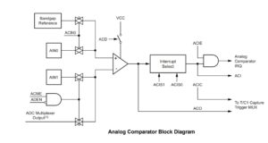
As seen in the block diagram above, AIN0 (PD6) is the positive input of the comparator and AIN1 (PD7) is the negative input. The signals applied to these two pins are evaluated by the comparator.
If the signal in AIN0 is greater in magnitude than the signal in AIN1, the ACO output of the bit in the ACSR register will be set high. Otherwise, the bit will be set low.
There may be different signal sources for the two input pins. For the AIN0 positive input, the controller can be configured to use an internal reference band voltage. For the negative input AIN1, any of the analog input pins A0~A7 can be used as a source. Additionally, the comparator output can be used as is or can trigger the Timer/Counter1 input capture interrupt.
How to use the analog comparator
Using the Arduino analog comparator is relatively simple, but first, identify the comparator pins on the board. Since each type of Arduino board is different, the assignment of pins to the positive and negative inputs of the comparator is also different.
Specific pins on each board are designated for analog conversion. These are analog input pins that are numbered (like A0, A1, etc.) or labeled with '~' or 'AC'. Connect the input signals to the comparator pins. One of the input pins must also be connected to a fixed reference signal. The other input is connected to the signal, which will be compared and monitored.
Then configure the comparator settings such as reference voltage, interrupt mode, and input capture. Associated records are defined in the user program or in libraries and library functions can be used. Programming the comparator with the support of a library is usually easier, as it does not require knowledge of the registers to configure the comparator properly.
Lastly, read the comparator output. The output is available through a function or variable of a specific library's user program. Otherwise, you may need to read the status of an associated register or a bit that indicates the output of the comparator.
The output clearly indicates whether the input signal is of greater or lesser magnitude than the fixed reference voltage. The output can then be used for decision making or triggering specific actions in the user program. The output can also trigger an input capture similar to an Arduino UNO Timer/Counter1 interrupt.
Arduino Registers
In the ATmega328P, there are five analog comparator registers as follows:
1. ACSR (Analog Comparator Control and Status Register)
2. DIDR1 (Digital Input Disable Register 1)
3. ADCSRA (ADC A Control and Status Register)
4. ADCSRB (ADC control and status register B)
5. ADMUX (ADC multiplexer selection register)
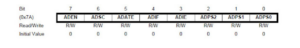
ACSR register : the most important register, which is used to configure the analog comparator and monitor the associated flags. The record has the bitmap below.
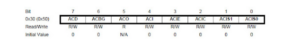 The Analog Comparator Disable (ACD) bit enables or disables the analog comparator. If the bit is set, the analog comparator will be disabled. Otherwise, the analog comparator will be enabled. Disabling the analog comparator reduces microcontroller power consumption.
The analog comparator bandgap selection ( ACBG ) bit is used to select the positive input of the comparator. If the bit is set, a fixed bandgap reference voltage is used as the positive input. Otherwise, the input at AIN0 is used as the positive input of the comparator.
The analog comparator output ( ACO ) is the comparator output flag. If the voltage at AIN0 is greater than at AIN1, the flag will be activated. Otherwise, it's clean.
The analog comparator interrupt ( ACI ) flag indicates the state of the analog comparator interrupt. The flag is set whenever an interrupt occurs.
Analog Comparator Interrupt Enablement ( ACIE ) enables or disables the analog comparator interrupt. If the bit is set, the analog comparator interrupt is enabled. Otherwise, it is disabled.
Activating analog comparator input capture ( ACIC ) enables or disables the Timer/Counter1 input capture function triggered by the analog comparator output. If the bit is set, input capture is enabled. Otherwise, it is disabled.
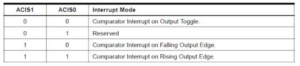
ACIS1 and ACIS0 are analog comparator interrupt mode selection bits. These bits are used to configure the interrupt type of the comparator. If both bits are cleared, comparator interrupt on output switching will be selected. If ACIS1 is unchecked and ACIS0 is set, the state is reserved and will not be used. If ACIS1 is set and ACIS0 is cleared, the comparator interrupt on the falling output edge will be selected. If both bits are on, the comparator interrupt on the rising edge is selected.
DIDR1 register : has only two bits, AIN0D and AIN1D, with the following bitmap:
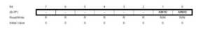
If AIN0D is set, the digital input buffer for AIN0 will be disabled. If AIN1D is set, the digital input buffer for AIN1 will be disabled. Disabling the digital input buffer for these pins is another way to save controller power consumption.
ADCSRA Register : An important bit for analog comparison in this register is ADEN. It has the following bitmap:
The ADEN bit is used to enable or disable the Arduino ADC. If it is set, the ADC is enabled. Otherwise, the ADC will be disabled. The rest of the bits in this register configure analog-to-digital conversions in the Arduino and have nothing to do with analog comparison. (For example, the ADSC bit is used to initiate analog-to-digital conversion, and the ADIF is used as the ADC interrupt flag, etc.)
ADCSRB Register : An important bit for analog comparison in this register is ACME. It has the following bitmap:
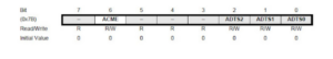
The ACME bit determines whether or not to use the multiplexed analog input. If ADEN is unchecked (i.e. ADC is disabled and ACME is configured), analog input pins A0~A7 will be used for negative comparator input. The remaining bits in this register refer to the analog-to-digital conversion and have nothing to do with the analog comparator.
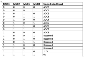
ADMUX register : the MUX3:1 bits of the ADMUX register are used to select which analog input A0~A7 should be used as a negative input for the comparator. It has the following bitmap:
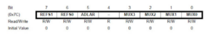
The analog source is selected based on the status of the MUX3:1 bit, as shown in the table below.
The rest of the bits in this register are related to analog-to-digital conversion and have nothing to do with the analog comparator.
Applications of an analog comparator
The Arduino analog comparator is typically used for the following tasks…
Threshold detection : Analog comparison in Arduino is often used to detect whether a voltage exceeds a certain threshold level. The input voltage is compared to a fixed reference voltage. Next, the output of the analog comparator is monitored to see if the input voltage exceeds the fixed reference voltage. Threshold detection is commonly used to detect the output of an analog sensor and whether it has exceeded a predefined value.
Digital to Analog Conversion : The Arduino comparator is used in conjunction with a resistor-ladder network, which is connected between the output pin of the comparator and a fixed reference voltage. Intermediate connection points are then used to create the desired digital voltage levels. This technique is typically used to generate analog reference voltages for the ADC.
PWM : An analog comparator can generate pulse-width modulated signals to control a motor, a faded LED, or other PWM applications.
How to configure the ATmega328P analog comparator
When using an analog comparator, only a few registers must be configured. It depends on the positive and negative input sources of the comparator and the application of its output.
In normal operation, when the positive and negative comparator signals are applied through AIN0 and AIN1 respectively, only the ACSR and DIDR1 registers must be configured in the user program.
For positive input of the comparator, the bandgap reference voltage can be used instead of the external input. When using the bandgap reference voltage as a positive input, the ACSR must be configured. The ACSR must also configure the comparator interrupt, interrupt mode, and input capture.
For negative comparator input, analog input pins A0~A7 can be used. To set the external analog input source A0~A7 to a negative input, the ADCSRA, ADCSRB and ADMUX registers must be configured.
In all cases, the DIDR1 register can be configured to enable or disable the digital input buffer for positive and negative comparator input.
Comparing signals
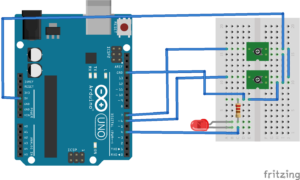
Now, let's program a normal analog voltage comparison using Arduino. To do this:
- Connect two voltage sources to the PD6 and PD7 pins of the Arduino UNO. Voltage can be applied through 10K potentiometers or voltage divider circuits.
- Connect an LED to the PD4 pin of the Arduino to check the status of the analog comparator.
- Note: the anode of the LEDs must be connected to the pin and the cathode must be connected to ground through a series resistor.
Upload the following sketch to the Arduino UNO.
null configuration {
DDRD = (1<
DIDR1 = (1<
ADCSRB &= ~(1<
CAA =
(0 << DCA) //Analog Comparator: Enabled
(0 << ACBG) // Clear ACBG to use external input for AIN0 +ve input
(0 << ACO)
(1 << ICA) // Clears the pending interrupt by setting the bit
(0 << ACIE) //Analog comparator interrupt disabled
(0 << ACIC) // Analog comparator input capture disabled
(0 << ACIS1) (0 << ACIS0); // Analog comparator interrupt mode: comparator interrupt at output
Toggle
}
empty loop {
if (ACSR & (1<
PORTD = (1<
other
PORTD &= ~(1<
}
When loading the above sketch, if the voltage at the positive input (INV0/PD6) is greater than the voltage at the negative input (INV1/PD7), the ACSR comparator output bit is set and the digital output at pin PD4 is set to HIGH, causing the LED to light up.
If the voltage at the positive input (INV0/PD6) is lower than the voltage at the negative input (INV1/PD7), the ACSR comparator output bit is cleared and the digital output at pin PD4 is set to LOW, causing the LED turns off.