There is no other tool available that helps in easy prototyping like Arduino. Any AVR microcontroller based board that follows the standard Arduino schematic and is flashed with the Arduino bootloader can be called an Arduino board. Arduino can be used as a standalone board, whose output or inputs can be taken from the boards or supplied to the board using convenient connectors. Digital and analog inputs and outputs are available on all Arduino boards. When it comes to programming the Arduino board, anyone who has basic knowledge of C programming can quickly start using the Arduino IDE.
Since the Arduino board can act as a standalone system, it must have capabilities to receive inputs, process the input, and then generate a corresponding output. It is through these inputs and outputs that the Arduino as a system can communicate with the environment. Arduino boards can communicate with other devices using standard digital input/output communication ports such as USART, IIC and USB, etc. This article explains how to use the digital input and output of the Arduino board with the help of a simple button as a digital input device and an LED as a digital output device.
It is assumed that the reader has gone through the Getting Started with Arduino project and I did all the things discussed in it.

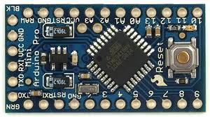
Fig. 2: Typical Arduino Pro-Mini board
This project also uses the Arduino Pro-Mini board and the same version of Arduino IDE 1.0.3.
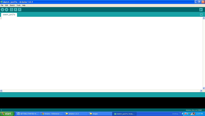
Fig. 3: Arduino IDE software window
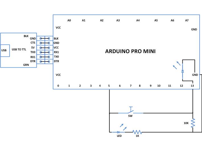
The digital output device in this particular project is an LED which is connected to pin number 5 of the Arduino board through a 1K current limiting resistor. A button is connected to pin number 13 using a pull down resistor. The code continuously reads the status of pin number 13 which has been configured as a digital output. Due to the presence of the pull down resistor the default value will be zero (the value when the key is not pressed). When the key is pressed, the value at pin 13 suddenly becomes logic high and the code detects the change and lights up the LED connected to pin number 5.
THE CODE
const int buttonPin = 13; // the pin number of the button
const int ledPin = 5; // the LED pin number
// variables will change:
int buttonstate = 0; //variable for reading the button status
null configuration
{
// initialize the LED pin as output:
pinMode(ledPin, OUTPUT);
// initialize the button pin as an input:
pinMode(buttonPin, INPUT);
}
empty loop
{
// read the state of the button value:
buttonState = digitalRead(buttonPin);
// checks if the button is pressed.
// if so, the buttonState is HIGH:
if (buttonState == HIGH)
{
//turn on the LED:
digitalWrite(ledPin, HIGH);
delay(100);
}
other
{
//turn off the LED:
digitalWrite(ledPin, LOW);
}
}
All Arduino code has two basic functions, namely setup and loop explained in the First steps with Arduino project . In addition to these functions, there are four other library functions used in this project, namely pinMode , digitalRead , digitalWrite and delay .
pinMode
The pinMode function is a built-in function used to define a specific pin as input or output. The first parameter is the pin number and the second parameter suggests whether the pin should be input or output.
For example, to make pin number 5 as output
pinMode (5, OUTPUT);
To make pin number 6 as input
pinMode(6, INPUT);
digital writing
digitalWrite is another function that can be used to write a digital value (logic 0 or logic high) to a certain pin that has already been output using the pinMode function.
For example, to make pin number 5 as logic high
digitalWrite(5, HIGH);
And to leave the same logic pin low
digitalWrite(5, DOWN);
digital reading
digitalRead is a function that is used to read the value (logic0 or logic1) on a pin that has already been inserted using the pinMode function. Suppose if pin number 13 is an input pin, then one can use the pinMode function to store the value of pin number 13 in a variable 'var' as shown in the following example;
var = digital reading(13);
The function returns the value 0 or 1 according to the voltage on pin number 13 in the 'var' variable, which can be integer or character.
delay
The delay function is a very useful function for almost all projects and can generate a delay in milliseconds between code steps.
For example, to generate a 5 second delay,
delay(5000);
Once the coding is complete, check the code and upload it to the Arduino board as mentioned in the project how to get started with arduino .
Project source code
 ###


 /*================================= EG LABS =========================== ==========================


Turns on and off a light emitting diode(LED) connected to digital

 pin 5, when pressing a pushbutton attached to pin 13.


The circuit:

 * LED attached from pin 5 to ground through a 1K resistor

 * pushbutton attached to pin 13 from +5V

 * 10K resistor attached to pin 13 from ground

 //================================= EG LABS =========================== ==========================*/


 // constants won't change. They're used here to

 // set pin numbers:


 const int buttonPin = 13; // the number of the pushbutton pin

 const int ledPin = 5; // the number of the LED pin


 // variables will change:

int buttonState = 0; // variable for reading the pushbutton status


 void setup

 {

 // initialize the LED pin as an output:

 pinMode(ledPin, OUTPUT);

 // initialize the pushbutton pin as an input:

 pinMode(buttonPin, INPUT);

 }


 void loop

 {

 // read the state of the pushbutton value:

 buttonState = digitalRead(buttonPin);


 // check if the pushbutton is pressed.

 // if it is, the buttonState is HIGH:

 if (buttonState == HIGH)

 {

 // turn LED on:

 digitalWrite(ledPin, HIGH);

delay(100);

 }

 else

 {

 // turn LED off:

 digitalWrite(ledPin, LOW);

 }

 }

 ###
Circuit diagrams
| Circuit Diagram Using Digital Input-Digital Output-Arduino |
 |
Project Components
- Arduino ProMini
- LED
- Resistor
Project video


