Although microcontrollers are purely digital devices that operate on logic0 and logic1 voltages, they are commonly found interfacing with analog systems or circuits. The microcontroller can read the analog input voltage by sampling it and converting it into its digital values with the help of Analog to Digital Converter (ADC). The microcontroller can also generate an analog voltage on any external device with the help of pulse width modulated (PWM) waves. Most microcontrollers have built-in PWM module and ADC modules that help them in reading analog voltage inputs and generating analog voltage outputs on an external device. Those who have done some basic experiments with PWM and ADC modules know how complex it is to configure them, initialize them, and make them work correctly together. All these things are simplified on an Arduino board in such a way that even a beginner can quickly interface it with analog input and output devices. Arduino can be used as a standalone board, whose output or inputs can be taken from the boards or supplied to the board using convenient connectors. Digital and analog inputs and outputs are available on all Arduino boards. Arduino boards can communicate with other devices using standard digital input/output communication ports such as USART, IIC and USB, etc.
In this project the Arduino pro-mini board is used which is programmed with the help of Arduino IDE version 1.0.3 on Windows operating system.

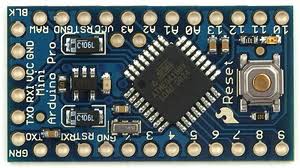
Fig. 2: Typical Arduino Pro-Mini board

Fig. 3: Arduino IDE software window
Another hardware that can perform USB to TTL conversion is used to load the program onto the Arduino board.

4: External USB to TTL converter board for Arduino programming and serial communication
It is assumed that the reader has gone through the project how to get started with Arduino and I did all the things discussed in it. The Arduino Pro-Mini board can have a maximum of eight analog pins that can be configured as analog input pins. The pins are marked on the board as A0, A1, A2,… A7. In fact, they are the input channels of the integrated ADC, which can read the analog value and convert it to the digital equivalent. Some pro-mini boards have fewer analog pins. In this particular project, analog pin 0 and analog pin 1 are using only one of them as an analog input and the other as an analog output. The variable pin of a potentiometer is connected to the analog pin; in this project pin A0. The other two pins of the potentiometer are connected to VCC and GND so that as the variable moves, it can divide all the supply voltage and provide it as analog input voltage to the Arduino board.
The Arduino Pro-Mini board typically has six analog output pins that can be used to generate analog output voltage. The pins marked on the board as 3, 5, 6, 9, 10 and 11 can act as analog output. In fact, they are the output channels of the integrated PWM module that can generate the analog output voltages. An LED is connected to the analog output pin through a current limiting resistor; in this project it is connected to pin 5. The code continuously reads the value from the potentiometer and writes the corresponding value to change the brightness of the LED connected to pin 5.
THE CODE
constintanalogInPin = A0; // Analog input pin to which the potentiometer is connected
constintanalogOutPin = 5; // Analog output pin to which the LED is connected
internal value = 0;
input value = 0;
null configuration
{
;
}
empty loop
{
// read the analog value:
valuepot = analogRead(analogInPin);
// maps it to the analog output range:
output value = map(pot value, 0.1023, 0.255);
// change the analog output value:
analogWrite(analogOutPin, output value);
// wait 2 milliseconds before next loop
// for the analog-to-digital converter to stabilize
// after last reading:
delay(2);
}
The details of the setup function, loop are already explained in the project how to get started with arduino . The details of other basic functions such as delay are explained separately in the project how to use arduin digital input and digital output . There are functions in the above code that can perform analog reading and writing, namely analogRead and analogWrite respectively. The details of the functions are discussed in the following section.
analog reading
This function can read an analog value from an analog pin mentioned in its argument and return that value. Suppose if there is a variable 'var' from which the value of analog pin A0 needs to be read, one can use the analogRead function as shown below;
var = analogreading(A0);
The above instruction will enable the Arduino microcontroller's built-in ADC, which then converts the analog value into its 10-bit digital equivalent and then stores it in the 'var' variable. The variable 'var' is expected to be of type integer.
analog writing
This function can write an analog value to an analog output pin mentioned in its argument to generate the equivalent voltage on that pin. For example, you can use the analogWrite function to generate a voltage equivalent to the value 100 on an analog output pin 5, as shown below;
analogWrite(5, 100);
The above instruction will actually write the value 100 to an 8-bit PWM module which will generate a corresponding width modulated waveform on pin number 5 so as to generate the equivalent voltage on the device connected to that pin.
map
map is a built-in function that can be used to map the value from one range to another. For example, the Arduino ADC outputs 10-bit values, but the Arduino PWM module can output 8-bit equivalent waveforms. If there is a need to directly write the value of the analog input to the analog output, you can use the map function as follows;
var = map(potvalue, 0, 1023, 0, 255);
The above instruction will convert the value that is in the range of 0 to 1023 (the 10-bit ADC output) to the range of 0 to 255 (the 8-bit PWM input range) and store it in a variable 'var' . The variable 'var' can be of type integer or character.
Now, once the coding is complete, you can check and upload the code to the Arduino board as explained in the Getting Started with Arduino project and you can see that the brightness of the LED varies as the potentiometer variable moves.
Project source code
 ###


 /*============================= EG LABS ================== =================//


 Demonstration on how to use analog input and output of an Arduino board


 The circuit:

 * Potentiometer attached to analog input A0

 * one side pin (either one) to ground

 * the other side pin to +5V

 * LED anode (long leg) attached to digital output 5

 * LED cathode (short leg) attached to ground through a 1K resistor


//============================= EG LABS ================== =================*/


const int analogInPin = A0; // Analog input pin that the potentiometer is attached to

 const int analogOutPin = 5; // Analog output pin that the LED is attached to

 int potvalue = 0;

 int outputvalue=0;


 void setup

 {

 ;

 }


 void loop

 {

 // read the analog in value:

 potvalue = analogRead(analogInPin);

 // map it to the range of the analog out:

 outputvalue = map(potvalue, 0, 1023, 0, 255);

 // change the analog out value:

 analogWrite(analogOutPin, outputvalue);

 // wait 2 milliseconds before the next loop

 // for the analog-to-digital converter to settle

 // after the last reading:

 delay(2);

 }

 ###
Circuit diagrams
| Circuit diagram using analog input, analog output and Arduino board | 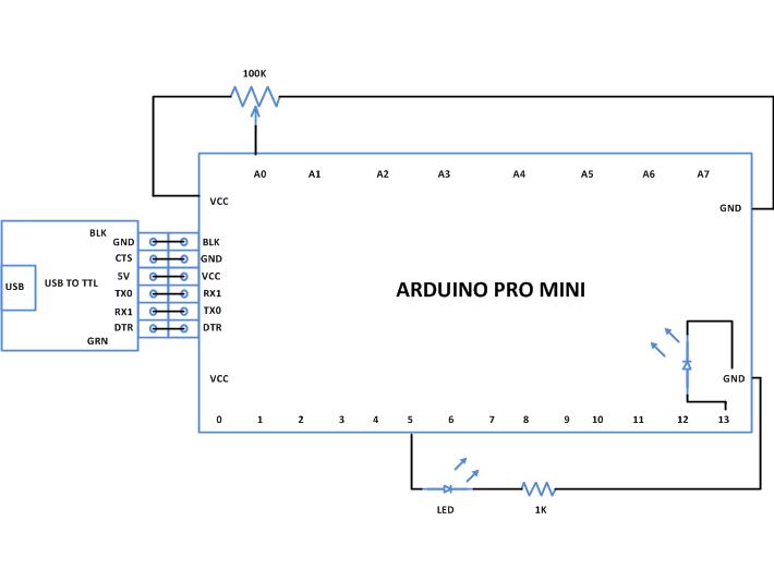 |
Project Components
- Arduino ProMini
- LED
- Resistor
Project video