
Biometric devices are the backbone of modern security and access systems. The most commonly used biometric device is a fingerprint reader. Fingerprints are unique identifiers that cannot be easily forged. Optical fingerprint sensors are widely used in security systems as they are low cost compared to capacitive and ultrasonic scanners. Optical fingerprint sensors digitize fingerprints by capturing a digital image and saving it to a fingerprint template. Fingerprint templates are stored in flash memory and compared with new scans to detect a valid access attempt.
Most optical fingerprint readers have a TTL UART port and a USB port to communicate with a computer system. The computer system, a microcontroller, a single board computer, a desktop system, or a server can control the fingerprint reader to register a fingerprint ID, compare and match a scan with registered fingerprint templates, or even download a stored or scanned fingerprint template.
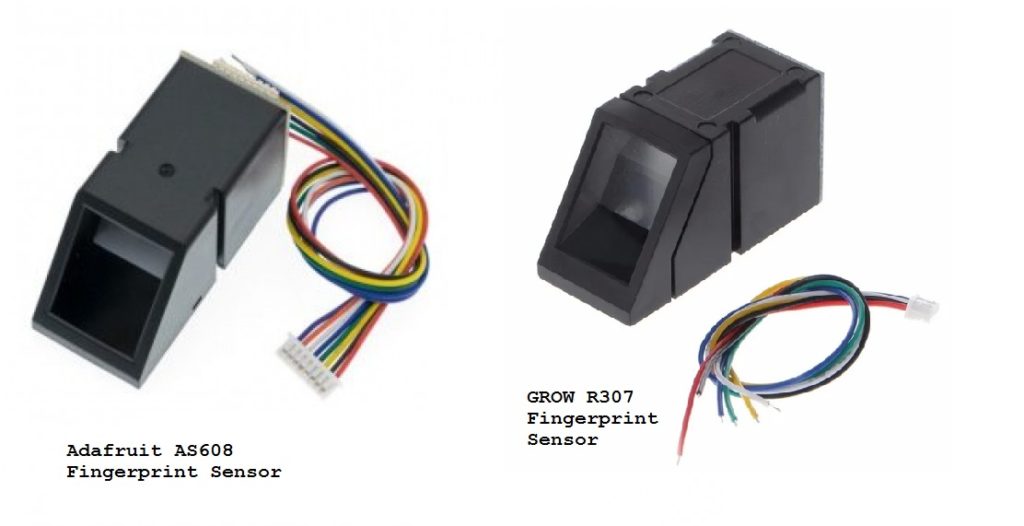
Adafruit and R30X fingerprint sensor examples
The Adafruit AS608 fingerprint reader is one of the most popular optical fingerprint readers and is often used with Arduino and other embedded development boards. The R30X series of fingerprint sensors from a Chinese supplier called Hangzhou Grow Technology Co., Ltd. is an alternative to the Adafruit sensor. Popular fingerprint readers in this series include R300, RR301T, R302, R303, R303T, R305, R307, R308 and R311. Some of these R30X sensors are capacitive. Despite different fingerprint scanning technologies, all R30X sensors have the same interface and set of commands. R305 and R307 are the most popular optical fingerprint sensors in this series. Interestingly, the Adafruit fingerprint sensor library works well with both the Adafruit fingerprint sensor and the R30X sensors. In this tutorial, we will demonstrate registering a fingerprint ID and matching fingerprints using the R307 module.
How optical fingerprint readers work
The skin of the palm has friction ridges for gripping and holding things, and the pattern of these ridges and valleys is also present on the fingertips. A miracle of nature is that this pattern of ridges and valleys is unique to each individual. An impression of our fingerprints is left whenever we grab or hold something due to oil, moisture, dust and dead skin cells. These fingerprint objects are called latent fingerprints.
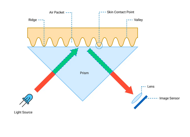
Operation of optical fingerprint sensors.
Optical fingerprint readers use the principle of Total Internal Reflection (TRI). An optical fingerprint reader consists of a prism. On one face of the prism there is an LED light source. Light enters the prism at a certain angle, so it is reflected off the adjacent face and exits through the third face, where a lens and image capture sensor are placed.
When no finger or print is placed on the sensor, the light transmitted by the LED source is completely reflected and the image sensor captures a single image. However, when the fingertip is placed over the scanner, some of the light is reflected, while some of the light leaks along the surface of the prism face. These are called Evanescent Waves.
Different materials have different reflection rates and interact differently with evanescent waves. When the fingertip is placed over the scanner, the protrusions are in firm contact with the scanner surface while the valleys are filled with air pockets. The skin and air have different reflection rates causing different evanescent waves, called Frustrated Total Internal Reflection (FTIR). As a result of different evanescent waves from crests and troughs, the intensity of the total internally reflected light changes according to the pattern of the ridges and troughs. The image sensor captures a high contrast image by recording the changed pattern of light intensity, capturing the pattern of ridges and valleys as a high contrast digital image.
The high-contrast digital image is stored in Flash memory as fingerprint identification according to a predefined template. The model indicates the presence of ridges or valleys at predefined positions in a captured or digitized image. Any fingerprint sensor is designed to perform two processes – essentially registration and matching. The process of reading the fingerprint and storing it according to a predefined template is called registration. A fingerprint reader can register multiple fingerprint IDs depending on the flash memory and integrated controller. The registration process usually involves fingerprint confirmation, so you need to scan your fingerprint twice. Fingerprint IDs store the images in the module.
In fingerprint matching, a new scan is compared to the stored fingerprint templates, and if it has the same template as any of the stored prints, the match is confirmed. Otherwise, the scan will be rejected as no match. If the active finger is matched with a specific fingerprint ID, this is called a 1:1 match. If the active finger is compared to match all fingerprint templates stored in the module, this is called a 1:N match.
R307 fingerprint sensor
R307 is one of the optical fingerprint scanners from Hangzhou Grow Technology Co., Ltd. The scanner operates at a voltage of 4.2V~6V and 50mA with a storage capacity of 1000 prints. The R307 has UART and USB 2.0 interfaces to communicate with a computer system at a baud rate in multiples of 9600 bps. It is capable of 1:1 and 1:N matching with FAR (false acceptance rate) less than 0.001 percent. The module can scan an active finger in less than 0.5 seconds and supports five security levels (1~5; 5 is the highest). The operating temperature range of this sensor is -10˚C to 40˚C, making it deployable in most locations.
R307 Sensor Assembly
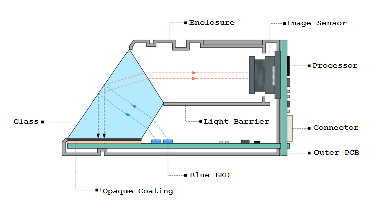
Physical assembly of R30X fingerprint sensors
The R307 has a glass cover where your fingertip can be placed for scanning. A prism is placed below the glass top. The inside of the sensor is divided into two parts by a light barrier. On one side of the light barrier is a PCB consisting of four blue LED lights. On the other side of the light barrier is an image sensor connected to a processor. The external PCB contains the processor, connector and other circuit elements. The prism, together with the blue LEDs and an image sensor, is arranged in such a way that the light transmitted by the blue LEDs is reflected internally through the prism to the image sensor.
R307 sensor pinout
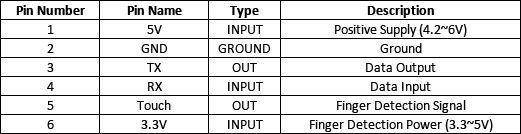
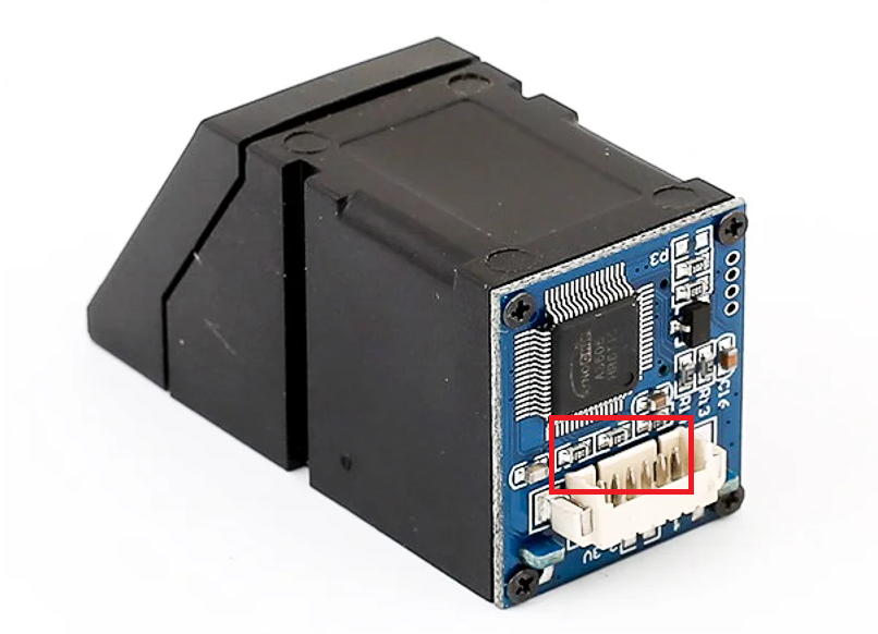
The R307 fingerprint sensor connector has six terminals. The pin configuration of this connector is as follows.
The pins are arranged in the connector, as shown in the image below.
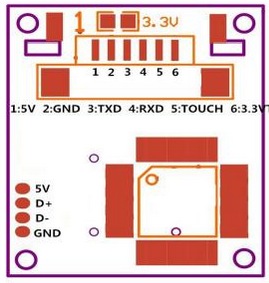
R307 Fingerprint Sensor Pin Configuration
The sensor can be operated at either 5V or 3.3V DC. If the sensor is connected to a 3V3 controller, the 3.3V jumper must be shorted. If interfacing with a 5V controller, the jumper must be left open.
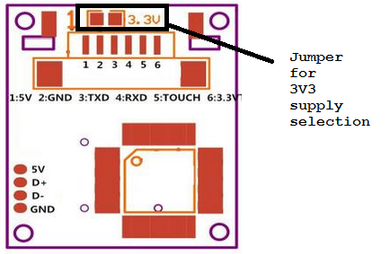 The scanner can communicate with a computer/controller using TTL UART and a USB interface. When connected via a USB port, a virtual COM port is created. It should be noted that pin 6 is the supply voltage for finger detection. If pin 6 is connected to a 3.3V source, the pin 5 output goes HIGH when an active finger is placed over the sensor. It is useful for manual finger scanning; otherwise, the sensor will start searching for a scan after a few seconds after initialization. It is important to select the appropriate supply voltage on the fingerprint reader. Higher voltage may damage a 3V3 controller or its GPIO pins.
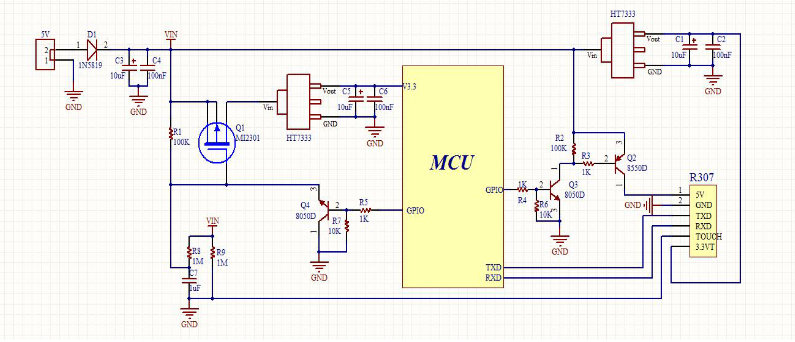
R307 sensor circuit
The R307 fingerprint reader controller chip is AS606 from Synochip. AS606 is a microcontroller capable of processing digital signals. For touch detection, the sensor has IC TTP233D from Tontek. The external PCB has the following circuit diagram.
R307 Records
The R307 scanner has built-in flash memory and plenty of registers and buffer memory to store configuration and fingerprint data. Some of the important registers of R307 are explained below.
Notepad: This is a 512-byte non-volatile flash memory organized into 16 pages of 32 bytes each. All memory is written or updated at once.
Image Buffer: It is a RAM used to temporarily store a digital image of the fingerprint. It stores a BMP image with dimensions 256 X 288, where each pixel is stored as a byte.
Character file buffer: It is used to store a high-contrast processed image of the fingerprint. There are two character file buffers of 512 bytes each, and they store two character files from two consecutive scans. The two scans are combined to form a template file that represents the final version of a fingerprint. Template files are stored in the fingerprint library.
Fingerprint Library: It is a built-in flash memory where 1000 fingerprint templates can be stored. Template files are stored sequentially in the library.
System Configuration Registers: It is a 16-byte register bank that stores configuration data and status flags. The register bank starts a 2-byte status register, followed by a 2-byte system identifier code, 2-byte library size, 2-byte security level, 4-byte device address, data packet size 2 bytes and 2 bytes device address. transmission multiplier. The status register is defined as follows.
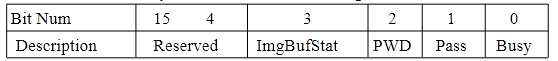
Where, Busy = 1 if the system is executing the command, otherwise Busy = 0 if the system is free. Pass = 1 if a matching fingerprint is found, otherwise Pass = 0 if the fingerprint is not found. PWD = 1 if the handshaking password is verified, otherwise PWD = 0 if the password does not match. ImgBufStat = 1 if the image buffer contains a valid image, otherwise ImgBufStat = 0 if the image is not processed.
The System Identifier Code has a fixed value that identifies the R30X series module. R307 has a code of 0x0009. The library size indicates the number of fingerprint templates the module can store. For R307, it is 1000. The security value determines the fingerprint matching threshold. It can be from 1 to 5, where 5 is the highest security level that provides minimum FAR and maximum FRR. FAR is the probability of identifying a weakly matched fingerprint as positive. FRR (false recognition rate) is the probability of identifying a wrong fingerprint as negative. At level 5, FAR is the highest and FRR is the lowest. This is the most rigorous level of fingerprint matching. The device address is by default 0xFFFFFFFF. It can be modified with the SetAddr command. Data Packet Size determines the maximum size of data sent in a single packet. Its value can be 0~3, where 0 = 32 bytes, 1 = 64 bytes, 2 = 128 bytes and 3 = 256 bytes. The Baud Multiplier defines the speed of data communication with a computer system. It can be from 1 to 12 in multiples of 9,600 bps with a minimum baud rate of 9,600 bps and a maximum of 115,200 bps.
R307 communication protocol
The scanner can communicate data with a computer system using a UART or USB interface. Both interfaces use a common communication protocol. Data is communicated in the form of packets. Each packet is divided into 10-bit frames. A frame starts with a start bit of 0 followed by a byte and ends with an end bit of 1. A packet is divided into the following frames.

The Header is 2 bytes long and has a fixed value of 0xEF01. The high byte is always sent first. The Address is the 32-bit device address of the scanner. The module accepts a command or data only if the address is correct. The default device address is 0xFFFFFFFF. The packet identifier determines the packet type. It is 0x01 for command, 0x02 for data, 0x07 for acknowledgment packet, 0x08 to indicate the end of the data transfer packet. A command packet must follow a data packet. The confirmation packet is sent from the module to the computer system. Packet length indicates the size of the packet contents, including a checksum byte. Package contents can be a variable-length command, data, or parameter, as indicated by Package Length . Checksum is the arithmetic sum of all bytes in Packet Identifier , Packet Length, and Packet Content .
The R307 supports the following instruction set.
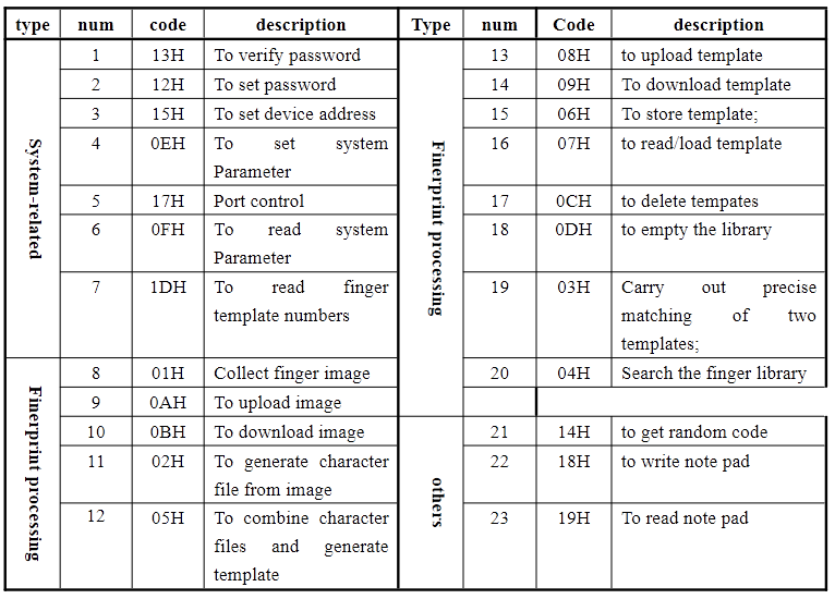
R307 Commands
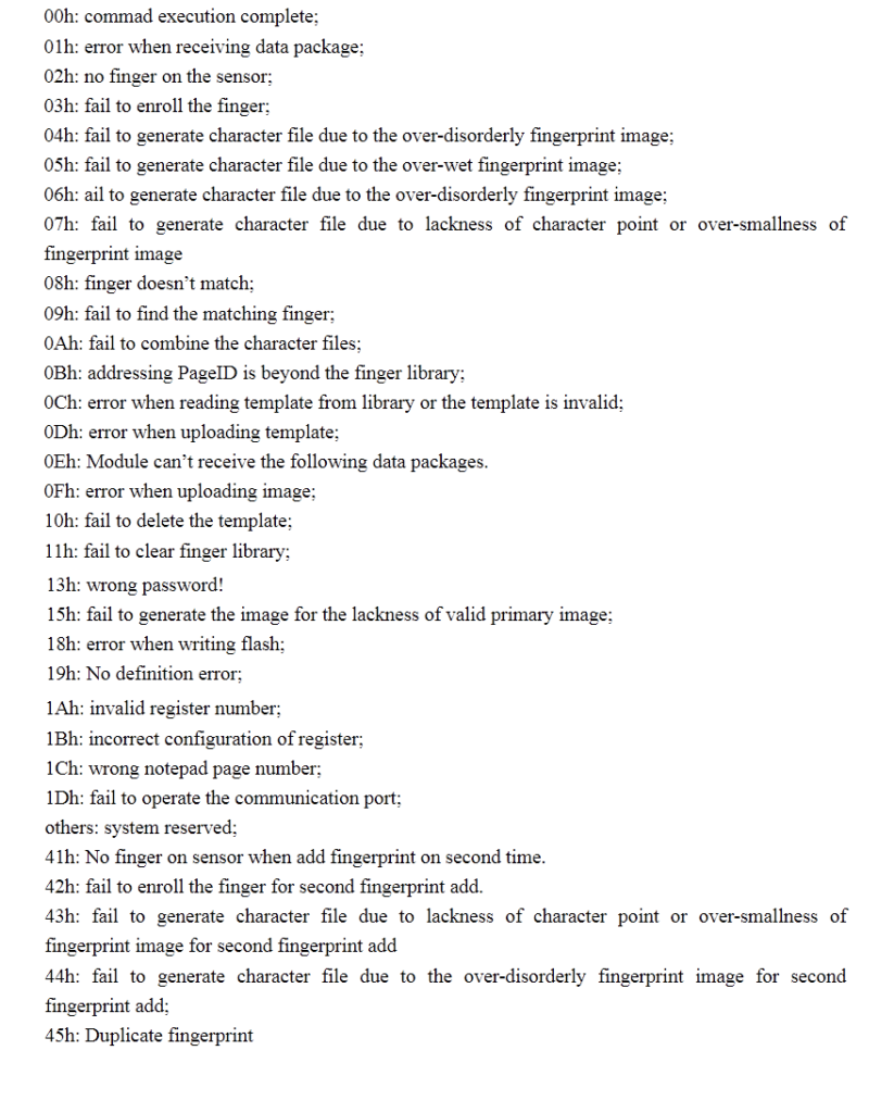
In response to a command from the computer system, the scanner sends back an acknowledgment packet containing the result and status of the command execution. Each command has a set of expected response codes called confirmation codes. The following is a list of confirmation codes for R30X modules.
Making a Simple Fingerprint Scanner
A fingerprint reader involves two processes – fingerprint registration and fingerprint matching. Let's now scan and match fingerprints using the R307 module. With this simple knowledge of fingerprint registration and matching, we can build any biometric security or access system.
Required components
- Adafruit Fingerprint Scanner or R307 Fingerprint Scanner x1
- Arduino UNO x1
- Male Header x1
Required tools
- Soldering Iron
- welding wire
Circuit Connections
The sensor comes with a connector cable with flexible wires with open ends on one side. The ends of the wires need to be soldered with a male connector to be connected to a breadboard or Arduino. Firstly, solder the cable wires with male connectors. Now insert the connector cable into the fingerprint reader header. It is easy to insert the connector cable as the header has clearly marked cuts for cable insertion.
 Connect the 5V pin and ground of the scanner with 5V output and any ground pin of the Arduino UNO respectively. Connect the Rxd and Txd of the scanner to the D2 and D3 pins of the Arduino UNO respectively.
Installing the Adafruit fingerprint sensor library
Navigate to the library manager in the Arduino IDE and search for the Adafruit fingerprint library. Install the Adafruit fingerprint scanner library. This library works well for both Adafruit fingerprint readers and R30X fingerprint readers.
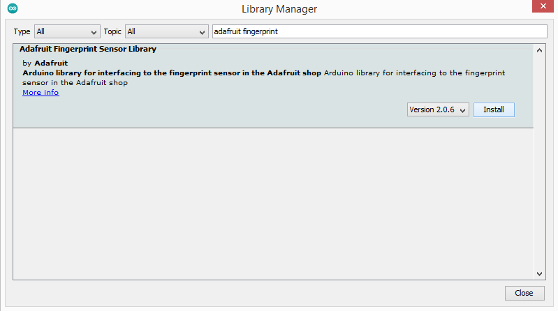
Adafruit Fingerprint Scanner Library
Registering a fingerprint ID
To register a fingerprint to the module, navigate to Files -> Examples -> Adafruit Fingerprint -> Register. Load the code into Arduino and run Serial Monitor. Select the baud rate to 9600. If the fingerprint reader is properly connected to the Arduino, a prompt to enter a fingerprint ID will appear on the Serial Monitor. Enter a valid fingerprint identification number and place your finger on the scanner. The scanner will ask you to scan your fingerprint twice. If the scan is successful, the confirmation message will be displayed on the Serial Monitor.
Matching a fingerprint ID
You can scan an active finger against stored fingerprint templates. To match a fingerprint print to the module, navigate to Files -> Examples -> Adafruit Fingerprint -> Fingerprint. Load the code into Arduino and run Serial Monitor. Select baud rate to 9600. Place your finger on the scanner. If the scanner has a template stored for your finger, it will respond with your template's fingerprint ID. If your fingerprint is not stored in the module, it will respond “no match found”.
Extracting fingerprint templates
It is even possible to obtain the template files stored in the fingerprint module. Navigate to Files -> Examples -> Adafruit Fingerprint -> show_fingerprint_templates. Load the code into Arduino and run Serial Monitor. Select the baud rate to 9600. Serial Monitor will display all stored fingerprint templates one by one by their ID in sequential order.
Conclusion
The R30X and Adafruit fingerprint scanners are low-cost, easy-to-use biometric modules. They can be easily interfaced into a security or access system using UART or USB interfaces. The Adafruit library works with R30X and Adafruit fingerprint scanners and can be used directly for many hobby projects.