Relays are commonly used for switching purposes. There are many types of relays such as electromagnetic relays, thermal relays, reed relays, solid state relays and hybrid relays. A relay is basically an electronically operated mechanical switch intended to be used for switching. Electromagnetic relays are also of various types such as attraction type relay, induction type relay and magnetic latching relay. This tutorial deals with magnetic latching relays that must be used to switch the load between two DC power sources. Switching from one DC source to another takes some time, so it cuts off supply to the load for a short period of time. This tutorial discusses how to reduce switching time so that the load does not experience any interruption during the relay transition phase.
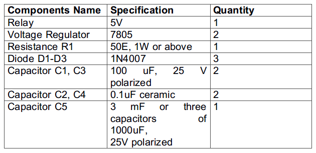
Required components –

Figure 1: Components required for the Relay Switching Time Reducer
Circuit Connections –
A latching type relay is used. The relay is intended to switch between two power sources. Both power supplies are considered 12V. Therefore, a 12V battery can be used as a power source. The batteries power is regulated to 5V DC using 7805 IC. For this, input power is applied to pin 1 of the IC and pin 2 is grounded. Power is then drawn from pin 3 of the IC. There are two 7805 ICs used in the circuit to regulate the power supply of the two supplies. One of the regulated power supplies is connected to the Normally Open (NO) point of the relay, while the other regulated power input is connected to the Normally Closed (NC) point of the relay. A load resistance (shown as R1 in the circuit diagram) is connected to the common point (C) of the relay. For quick switching of the relay response, a capacitor (shown as capacitor C5) is connected in parallel to the load R1.
While assembling the circuit, the following precautions should be taken –
1. Do not exceed the input voltage limit of the voltage regulator IC, as this may damage the IC. Check the IC datasheet for reference.
2. The nominal voltage of the input DC supply (12 V in this circuit) must be greater than the maximum required output voltage. This is due to the fact that the IC 7805 suffers a voltage drop of around 2V.
3. The voltage used to energize the relay (12V in this circuit) must be equal to or greater than the relay's rated voltage. Otherwise, the relay will not activate.
4. Always use the capacitor at the input of regulator IC (like capacitors C1 and C3 in the circuit diagram), as it can deal with mains noise and reduce unwanted ripples. Also use a ceramic capacitor (like capacitors C2 and C4 in the circuit diagram) in parallel with a high-value polarized capacitor. This will lower the overall ESR.
5. Capacitors used in the circuit must have a higher voltage rating than the input supply voltage. Otherwise, the capacitors may start to leak current due to excess voltage on their plates and explode.
6. Diodes D1 and D2 should be used as protection diode so that they can prevent the external capacitor C5 from being discharged through the voltage regulator ICs during an input short circuit. This will save the 7805 ICs from counter current.
7. A Flyback diode (shown as Diode D3 in the circuit diagram) should be used in the relay to prevent any back current in the circuit.
8. Use appropriate watt of resistor as load to avoid any damage to the resistor.
9. If a high current has to be drawn at the output, the voltage regulator ICs will heat up. Therefore, mount a suitable heat sink on the regulator ICs to dissipate excess heat.

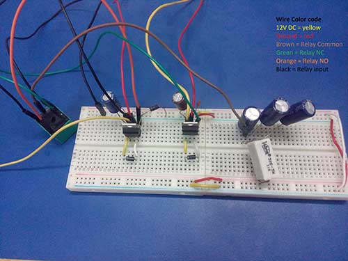
Fig. 2: Fast-switching magnetic latching relay prototype
How the circuit works –
The type of relay under consideration is magnetic latching relays. In this type of relay, the common pin (C) remains Normally Closed (NC) pin when its input pins are not energized. When power is supplied to the energizing pin or input pin of the relay, the relay is activated. The common pin of the relay is then switched to Normally Open (NO) pin and it takes some time to switch from NC pin to NO or vice versa.
In inverter circuits this relay is used to switch the load from one power source to another. Our 12V power supply energizes the relay and also provides input to the IC 7805 (shown along diode D1 in the circuit diagram). In this state, the load is connected to IC 7805. Whenever the 12V input supply is interrupted, the relay is de-energized. Now the load is connected to the other IC 7805 (shown along diode D2 in the circuit diagram), which is powered by another 12V source, but the load experiences some interruption when switching from one IC 7805 to another. This cuts power to the load for a short period of time which is equal to the relay switching time. But this switching time can be reduced by using capacitors.
A capacitor mainly has two basic functions. The most well-known function of capacitors is to filter the DC signal from unwanted voltage spikes and ripples. Therefore, these types of capacitors are called filtering capacitors. Another function of the capacitor that is of great importance, but less discussed, is the use of the capacitor as a reservoir. The term reservoir explains everything about this. Since the capacitor stores some charge, this accumulated charge can provide some energy. Therefore, capacitor is also used to retain electrical charge or to act as a source of energy. Due to this fact, the capacitor used as a charge reservoir is called a reservoir capacitor.
For fast switching of relays, a reservoir capacitor can be used which can handle fast transient responses at the output. This capacitor, if connected in parallel to the load, will store some charge. The stored charge can then be used to provide extra power to the load during the relay's transition period from NO to NC or vice versa. Therefore, a capacitor is used in parallel to the load (shown as resistance R1 in the circuit diagram). The required reservoir capacitor value can be calculated as follows –
Maximum current consumed by the load (I)
This can be calculated using ohms law.
V = I*R
Where
V = output voltage
I = current consumed by the load
R = load resistance
In the circuit, a 50 ohm load is used, so the maximum current drawn by the load is
I = V/R
I = 5/50
I = 100mA
Maximum output ripple voltage (dv)
Maximum ripple voltage is the maximum allowable voltage change at the output for which the capacitor is capable of meeting the desired voltage at the output.
In the circuit, the maximum ripple voltage is assumed to be 100 mV. Then,
dv = 100mV
Capacitor transient response time (dt)
This is the period of time during which power to the load must be supplied through the capacitor. This transient time must be equal to the relay switching time so that it can be compensated by the use of the capacitor.
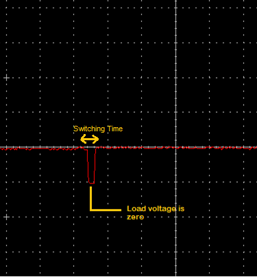
To calculate the relay switching time, the load output waveform (without the use of a capacitor) can be observed on the CRO. A waveform as shown below is observed –

Fig. 3: Graph showing relay switching time under normal conditions
As can be seen from the waveform above, at one point the voltage across the load is zero. Therefore this switching time must be reduced by using a capacitor. As observed in the CRO, the relay switching time is around 3ms.
Therefore, using the above values of maximum load current (I), maximum ripple voltage (dv) and transient response time (dt), the capacitor value required to reduce the switching time can be calculated as follows –
I = C*(dv/dt)
Where,
Maximum allowable ripple voltage, dv = 100mV
Transient response time, dt = 3ms
Desired output current, I = 100mA
C = Capacitance
Putting all the values,
C = (0.1*0.003)/0.1
C = 3mF
According to availability, three 1000uF capacitors connected in parallel can be used to make 3mF in total.
Testing the Circuit –
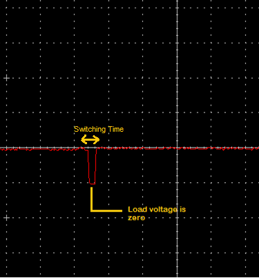
After connecting a 3 mF capacitor in parallel with the load and observing the output waveform at CRO, the following voltage waveform is observed –

Fig. 4: Graph showing reduced relay switching time after connecting the reservoir capacitor
This graph clearly shows that the relay switching time is now negligible and cannot even be measured. Now the load will not suffer any type of discontinuity in the power supply and will always receive a constant voltage supply.
Limitation of capacitor method –
As every circuit has some flaw along with its advantages. There are some disadvantages of this circuit as well. As seen to only consume 100mA current, the required capacitor value is 3 mF, which is very large. If it is necessary to draw a high current, the required capacitor value will be very large. So this makes the circuit expensive. Also, high value capacitors are not easily available.
In the next tutorial, learn how to test the MOSFET.

