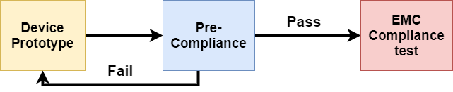
EMC testing is essential to obtain an electromagnetic emission and immunity test certification before releasing the product to the market. However, actual EMC tests are very expensive. Before going for actual EMC testing, the product must be tested in the EMC pre-compliance testing laboratory. Pre-compliance testing will mimic all tests performed in EMI/EMC testing labs to ensure the device will pass EMI/EMC compliance testing. Compliance testing labs are very expensive and difficult to pass; The cost of pre-compliance testing is cheaper than the actual cost of EMI/EMC compliance testing laboratories and will give approximately the same result.

Fig. 1 Block diagram for pre-compliance
This article covers how to perform pre-compliance testing with a focus on inexpensive or easy-to-configure testing to increase confidence in actual EMI/EMC testing.
As discussed in previous articles, EMI/EMC is an emission test to measure electromagnetic interference generated by the device. EMI testing or electromagnetic interference test limits depend on the standards set by country regulations. This also depends on the application of the product or device. For example, EMI/EMC testing for medical products is rigorous because medical equipment needs to be accurate in any condition. If medical devices generate any emissions, it will affect other medical devices and cause a false reading.
Types of EMI Pre-Compliance Tests
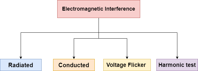
Figure 2 EMI Tests
The most common test performed on almost all devices is given in the block diagram. The reason for the EMI test failure could be the design of the PCB, shield, components and antennas. All of this leads to radiated and conducted emissions. This is why most EMI test failures occur in radiated and conducted emissions. Some method for setting up and measuring radiated emissions pre-compliance tests and conducted in the DIY laboratory are discussed below.
Radiated Emission Test
Two methods can measure radiation emission: a far-field method and a near-field method. Before knowing how to measure radiated emission in these fields, let's understand the difference between near-field and far-field measurements.
When oscillating electricity passes through a conductor, it induces a magnetic field. The induced magnetic field also creates an electrified field as shown below. The H field represents the magnetic field and the E field represents an electric field.

Fig. 3 E field (electric field) and H field
The device or equipment under test will produce E-field and H-field. The electric field has a high impedance in the vicinity of the product, and the magnetic field has a low impedance called the near field. At a certain distance, the electric field and magnetic field combine into the same impedance, which is a far field. The distance between the E field and the H field depends on the frequency of the waves.

Fig. 4 Near field and far field
Near-field radiated emission test
A measuring probe is used near the circuit to measure E-field waves and H-field waves. This is the cheapest measuring technique that designers use to get an idea of troubleshooting EMI tests on their products . Near-field testing is not as accurate as a far-field test, but it gives an idea of the EMI induced in the product during pre-compliance testing.
You will need a spectrum analyzer and measurement probes to measure near-field tests. There are some expensive spectrum analyzers available on the market, but a “pocket RF explorer” or USB spectrum analyzer dongle may work in some cases.

Fig.5 Spectrum analyzer
There are several types of near-field probes available on the market, or you can make your own. The image below is of electric field probes; There are two probes, one probe has a pointed tip and the other has a round tip. The rounded tip covers a wider area to measure the electric field in a circuit. Once the area where the electric field is generated is found, the small pointy probe will find the specific area of electric field. These probes are not sensitive to orientation, so measurements can be made in any direction.

Fig. 6 Electric field probe
Magnetic field probes have a loop to measure the magnetic field. There are two probes in the image below: one has a small diameter ring and the other has a large diameter ring. The large diameter ring measures the magnetic field over a wider area. After finding the magnetic field area, the smaller diameter probe can be used to find a specific area where electromagnetic fields are produced. These probes are very sensitive to orientation, so remember that readings will be taken in the same orientation and the probe ring parallel to the circuit will give a much better result.

Fig. 7 Magnetic field probes
This configuration needs an RF amplifier to amplify the signal coming from the probe to feed the spectrum analyzer. Standard probes come with the amplifier, but you can buy an RF amplifier PCB online for DIY probes.

Fig. 8 RF Amplifier
- DIY near H field probe
DIY probe can be made at a lower price than a real probe on the market. Just buy a semi-rigid cable and follow the diagram below. As in the diagram, make a wire loop and solder the inner wire with an outer shield, then solder it to make a loop as shown below.

Fig. 9 Internal diagram of the H field probe
After making this loop, cut the outer protection to create a space between the loop, as shown in the image below.

Fig. 10 section on the H field probe
Now dip it in some insulating paint or use some spray paint to get an insulating layer so it doesn't touch the open area of the circuit. Use a ferrite tweezer to avoid external noise, as shown in the image.

Fig. 11.1 DIY H field probe

Fig. 11.2 DIY H field probe
Far-Field Radiated Emission Test
Near-field measurement can only provide an idea of troubleshooting, but cannot read the emission accurately. This is why EMI/EMC testing laboratories use far-field radiated emission testing. This is expensive and a bit difficult to set up. Therefore, it is not easy to configure it in DIY precompliance labs, but some EMC precompliance labs provide this configuration. Far field testing can be performed in two types of areas.
- Open Area Test Sites (OTAs)
- Semi Anechoic Chamber (SAC)
-
Open Area Site (OTAs)
In open area testing, the setup occurs in an open area where minimal RF reflective objects are close to the area. The ground must be RF reflective and flat so that the antenna can obtain measurements directly from the EUT (equipment under test) and ground reflection.

Fig. 12 Open area site
The minimum distance between the EUT and the antenna must be 3 meters. If the distance is reduced to less than 3 meters, it will be considered near-field measurement, which will be less accurate. To obtain accurate readings at 30 MHz, one wavelength is 10 m, and at 100 MHz, one wavelength is 3 m.
-
Semi-Anechoic Chamber (SAC)
The semi-anechoic chamber is composed of metal walls with RF-absorbing material. The RF absorbing material absorbs the RF signal produced by the EUT. The size of the chamber depends on the pattern applied to the product. The distance between the antenna and the EUT is generally 3m, 5m and 10m.

Fig. 13 Semi-Anechoic Chamber
-
Spectrum Analyzer/EMI Receiver
As discussed in near field testing, every laboratory needs a spectrum analyzer to measure RF signals accurately. Ensure that the spectrum analyzer can cover all frequency bands that need to be investigated for EUT (e.g. 30 MHz to 5 GHz). Most Spectrum analyzers can measure “peak”, “average” and “near peak”, which helps with measurement.

Fig. 14 Spectrum analyzer
-
Antenna
The antenna is the most important component of far-field measurement. Lower frequency measurement will increase antenna size and cost, higher frequency measurement will reduce antenna size and cost. The antenna must be calibrated to obtain the exact antenna factors necessary for accurate field strength measurement. The maximum signal is received at a specific height so the antenna can move 4 to 6 meters high to obtain the maximum EMI signal. the cheapest antenna will not be able to measure low frequencies. The image shown below is the PCB based antenna for measuring frequencies from 0.6 GHz to 10 GHz.

Fig. 15 Far-field measurement antenna for 0.6 to 10 GHz
-
Turntable
In far-field measurement, both OATS and SAC need a turntable because the emission from the ESE device is generally directional. The table must be made of wood or any material that will not interfere with the measurement. The turntable must be rotated through 360 degrees of rotation so that measurement can be made in all directions of the EUT.

Fig. 16 Rotating table
-
TEM cell
This is another option for testing radiated emission testing. The TEM cell stands for transverse electromagnetic testing. TEM cells consist of the septum, a conducting plane in the middle, connected to a 50 Ohm load. The lower the TEM cell will capture, the higher the frequency and the higher the TEM cell will capture the lower frequency. It can be purchased or manufactured with suitable dimensions according to the frequency.

Fig. 17 TEM cell
Emission test carried out
The conducted emission test is not complicated like the radiated emission pre-compliance test because the equipment and setup required for this test is much smaller. You only need a spectrum analyzer and a LISN device for emissions pre-compliance testing. Above we have already discussed the radiated emission of different spectrum analyzer options. Now let's understand what LISN devices do?
LISN stands for Line Impedance Stabilization Network, this device is used for an emission test conducted. The device will be connected between the power and the EUT. This will help measure the RF noise generated by the EUT in the supply. The RF noise measured by the LISN device can be measured using a spectrum analyzer.

Fig.18 LISN
EMI/EMC Limits
EMI/EMC limits depend on the country's EMI regulatory standards. In the USA, interference is regulated by the FCC (Federal Communications Commission). The FCC categorizes devices into Class A and Class B. A Class A device is for industrial use and the device intended for residential use is in Class B. The table below shows the limits according to the FCC for Class A and Class B.

Fig. 19 FCC Standard Limits
In Europe, interference is regulated by CISPR. This is also a device categorized into two categories. The categories are the same as the FCC. Class A is for industrial devices and Class B is for residential devices. The limits for these devices under CISPR are set out below.

Fig. 20 Limits of CISPR standards