Contactless temperature measuring guns have become popular during the Covid pandemic. Several locations have used this device to ensure safety protocols. However, one of the disadvantages of currently available non-contact temperature measuring guns is that they measure body temperature – not the distance from the body (object) to the sensor.
The distance from the body to the sensor is the most important factor in correctly measuring temperature. The sensor used for non-contact temperature measurement in such weapons can only read the surface temperature of an object (in this case, the human body) accurately if the distance to the object is less than 5 cm. If we measure body temperature from 10 or 15 cm away, there is a possibility of error and inaccurate reading.
To ensure correct temperature reading, we must keep the gun sensor less than 5 cm away from the body. In this project, we will create a contactless smart temperature gun with some modifications and improvements in the sensor and software part to ensure its accuracy in measuring the correct temperature of the human body that considers distance as a parameter.
The gun will first measure the distance from the body, and when the body is less than 5 cm away, it will then measure its temperature. It does not measure temperature directly, but rather from a distance. If the body is far from the gun's sensor, it issues a message to get closer, and when the body is within 5 cm range, it measures the body temperature. This gives an accurate reading and fixes the problem of wrong body temperature reading.
We call this “ smart ” non-contact temperature measuring gun because it measures distance and reads body temperature multiple times, giving an accurate average value. It also reads body temperature beyond the normal range, providing an alert notification.
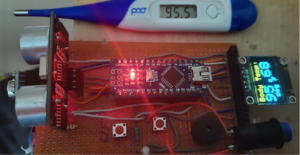
This gun is built using Melexis MLX90614 non-contact temperature measurement sensor, UDM HC SR04 sensor, Arduino, NANO and OLED. The body temperature measured with the gun is compared with a conventional digital thermometer.
Here is a snapshot of the prototype model.

A prototype of the smart non-contact temperature measuring gun.
Now, let's start building this weapon. First, we will cover the system block diagram.
System block diagram
The main building blocks of this system include:
- The non-contact temperature measurement sensor, MLX90614
- The Ultrasonic Distance Measuring (UDM) Sensor, HC SR04
- A 1-inch dual-color OLED screen
- The Arduino NANO development board
- Some other components like LED, a mini buzzer, a button, etc.

A block diagram of the completed prototype.
The MLX 90614 sensor: a non-contact temperature sensor that measures surface temperature within a short range of 5 cm and provides a temperature reading output to the Arduino microcontroller via IIC communication.
The HC SR04 UDM sensor: an ultrasonic distance measuring sensor that measures the distance to any object in front of it, providing a PWM output (pulse width varies depending on the distance to an object) to the Arduino microcontroller.
Arduino NANO: which performs these tasks:
- Reads and obtains human body temperature using the MLX sensor
- Measures the distance to an object (human body) using the UDM sensor
- Displays body temperature and distance on OLED screen
- Gives an audiovisual indication via LED and buzzer
- Receives user input from buttons
An OLED screen: This 0.96-inch dual-color (yellow and blue) mini OLED screen works on the IIC protocol. It displays the distance to the object, the surface temperature of the object and some messages.
Press buttons: there is one to take a reading (body temperature and distance) and another to change the temperature reading from ó C to ó F and vice versa.
An LED and a buzzer: Flashing LED and a buzzer “beep” sound are used for audiovisual indication of body temperature. The LED flashes when body temperature is measured and displayed on an OLED. At the same time, the buzzer beeps. The LED also flashes when the temperature reading changes from ó C to ó F and vice versa.
Before building the circuit, you will need to collect the necessary items.
Here is the list…
Required items:
1. The MLX90614 sensor

MLX90614 Sensor
2. The HC SR04 sensor

HC SR04 sensor
3. The OLED screen

OLED screen
4. The button (small and micro)

The button used in this project.
5. An LED

An LED
6. Arduino NANO

Arduino UNO
Circuit Diagram

The circuit diagram with Arduino and the OLED display.
The circuit is built with few components and can be quickly built on a general-purpose PCB (or also on a breadboard).
- The MLX90614 sensor has four pins (1) VIN (2) GND (3) SCL and (4) SDA. The sensor operates at 5V, so the VIN pin is connected to the Arduino's 5V output pin, and the GND pin is connected to the circuit and ground of the Arduino board. The SCL and SDA pins are serial clock and serial data pins for IIC communication. They are connected to the Arduino board's A4-SDA and A5-SCL pins, respectively.
- The HC SR04 sensor has four pins (1) Vcc (2) Gnd (3) Trig and (4) Echo. The sensor requires 5V, so its Vcc pin is connected to the 5V output pin of the Arduino board and the GND pin is connected to the circuit ground. The trigger pin (input) is connected to digital pin D2, and the echo pin (output) is connected to pin D3 on the Arduino board.
- Again, the OLED screen has four pins (1) Vcc (2) Gnd (3) SCL and (4) SDA. Its required operating voltage is 5V, so the Vcc pin is connected to the 5V output pin of the Arduino, and the GND pin is connected to the circuit and ground of the Arduino board. It also works on the IIC protocol, so its SCL and SDA pins are connected to the Arduino board's A4-SDA and A5-SCL pins, respectively.
- A small button is connected to pin A2* and a micro button is connected to pin D11 as shown.
- The buzzer is connected to pin A1* and the LED is connected to pin A0* as shown.
- A 9V battery (not shown in the figure) provides power for the entire circuit. It is connected to the Vin pin of the Arduino board. The Arduino board takes 9V input from the battery and provides 5V output using an integrated voltage regulator. This 5V output is supplied to all other components in the circuit.
* Note : Digital I/O devices (button, LED and buzzer) are connected with analog input pins because we are not using any analog input pins in this project. So we are using these analog input pins as digital I/O pins. But you can connect these devices to any digital pin (D0 – D13 depending on convenience.
Circuit operation
Before explaining the functioning and operation of a complete circuit, it is necessary to know how the different blocks work – such as the MLX sensor, UDM sensor, OLED display, etc. the OLED, please go to This article
The operation of the MLX90614 sensor
The MLX90614 is an infrared thermometer for non-contact temperature measurements. A low-noise amplifier, 17-bit ADC and powerful DSP unit are integrated into the MLX90614, enabling high thermometer accuracy and resolution. The IR-sensitive thermopile detector chip and signal conditioning ASIC are integrated in the same TO-39 can.
The thermometer is factory calibrated with an IIC bus (SMBus) digital output, giving full access to measured temperature across the entire temperature range(s) — with 0.02° C resolution. digital output to be pulsed. -width modulation (PWM). By default, the 10-bit PWM is configured to continuously transmit measured temperature in the range of -20 to 120°C, with an output resolution of 0.14°C.
The MLX90614 sensor can measure the temperature of an object without any physical contact. This is possible through the Stefan-Boltzmann Law , which states that all objects and living beings emit infrared energy. The intensity of the IR energy will be directly proportional to the temperature of that object or living being. Thus, the MLX90614 sensor calculates the temperature of an object by measuring the amount of infrared energy emitted by it.
The MLX90614 consists of two devices incorporated as a single sensor; one device acts as the sensing unit and the other acts as the processing unit. The sensing unit is an Infrared Thermopile Detector called MLX81101, which senses temperature. The processing unit is a single conditioning ASSP called MLX90302, which converts the sensor signal into digital value and communicates using the I2C protocol. The MLX90302 features a low-noise amplifier, 17-bit ADC, and a DSP, which helps the sensor achieve accuracy and resolution.
The sensor requires no external components and can be directly interfaced with any microcontroller. The power pins (Vdd and Gnd) can be used directly to power the sensor. The SCL and SDA signal pins are used for I2C communication and can be connected directly to the microcontroller operating at 5V logic.
The pins and functions 
As seen in the circuit diagram, these four pins are directly connected to the Arduino board. The Arduino microcontroller will get the direct digital value of body temperature from this sensor. However, the digital value provided by the sensor must be later calibrated with a standard medical digital thermometer for accurate body temperature measurement.
To interface the MLX sensor with Arduino and read the temperature of the object, we have to use its Arduino library readily available on Adafruit:
Adafruit_MLX90614.h
We have to install this library in Arduino IDE software.
Sensor testing and calibration
To test and calibrate the MLX sensor, follow the step-by-step procedure
1. Connect the sensor to the Arduino. Connect its four pins to Arduino as shown in the circuit diagram
2. Open the “mlxtest” example of this library (file-> example-> adafruit MLX90614 library -> mlxtest)
3. Load this program onto the Arduino board
4. The sensor will read the temperature of the object and display it on the serial monitor
5. Measure human body temperature using a sensor and write down the readings
6. Measure body temperature using a conventional (digital) medical thermometer to calibrate it. Compare the two values. If both are not equal, add some threshold value to the MLX sensor temperature readings.
For example, the MLX sensor reads body temperature as 91.0 ° F, and the thermometer reads the temperature as 95.5 ° F, so add a limit of 4.5 on the MLX sensor reading in the program as:
mlx.readObjectTempF + 4.5
- Now read the other person's body temperature using the sensor. Measure the temperature again using the thermometer and compare the two temperature readings. If they match, it's perfect, otherwise adjust the threshold value. Repeat this procedure five to six times and adjust the threshold value. You will get accurate readings of human body temperature with the MLX sensor.
After now understanding how the different blocks work, let's see how the complete circuit works.
- When battery power is supplied to the circuit, the initial message is displayed on the OLED as “ non-contact temperature measuring gun ”
- The button (small button) is pressed to measure body temperature.
- Once the button is pressed, the UDM sensor will start measuring the distance from the human body, which is displayed on the OLED screen.
- If the body is too far from the sensor, the message will be displayed: “ get closer. ”
- When the body reaches 5 cm or less, the MLX sensor begins reading the body temperature.
- It takes readings five consecutive times, calculates the average of the five readings and displays the final temperature value on the OLED. This process will take two to three seconds. The message is displayed on the OLED as “ Hold for 2-3 seconds read temperature ”
- The LED flashes several times and when the process is complete, the buzzer beeps. The final body temperature is displayed on the OLED screen.
- The final body temperature reading is displayed on the OLED as ó To ó C. It can be changed by pressing the micro button.
- Alternatively, pressing this button will change the temperature reading from ó C to ó F and vice versa. The LED flashes and the buzzer beeps every time it is changed.
- Lastly, if the body temperature exceeds the normal human body temperature range, such as 100 ° F (or 40 ° C), it gives an alert indication by flashing the LED. The buzzer will also sound three times.
The circuit is built on a general purpose PCB. Furthermore, it displays the circuit output results as temperature and distance measurement display on an OLED screen.
Here are some snapshots of component arrangements and circuit assembly…

The arrangement of the components and assembly of the circuit with the output.

The arrangement of the components and assembly of the circuit with output on the OLED.
This functioning and operation of the circuit is based on the program downloaded into the internal FLASH memory of the Arduino microcontroller (ATmega328). Next, it's time to go through the software program.
Software program
The program is responsible for performing all of the following tasks
- Measures distance to object (body) using UDM sensor
- Measures body temperature using the MLX sensor
- It displays distance and body temperature on an OLED
- Gives an alert indication through an LED and a buzzer if the body temperature is high
The program is written in C programming language using Arduino IDE, and is compiled and loaded into the internal FLASH of the Arduino microcontroller.
Here is the complete program code.