
Intel and ARM are the two popular processor families widely used in computing devices. Intel processors are mainly used in personal computers, while ARM processors are optimized for embedded system applications. State-of-the-art ARM processors can provide embedded system devices with as much computing power as most PCs. The Raspberry Pi is a low-cost minicomputer board designed to be used as a PC to provide computer education in remote schools, where expensive desktops are not available. Embedded system folks are interested in it as it uses a microcontroller based on ARM11 processor and unlike PC motherboard, Raspberry pi board offers many pinouts like GPIO pins, serial communication pins, etc. which allow that are used in embedded systems. system applications.
The Raspberrypi board uses a Broadcom controller chip which is a SoC (System on Chip). This controller has all the peripherals like timers, interrupt controller, GPIO, USB, PCM/I2S, DMA controller, I2C master, I2C/SPI slave, SPI0, SPI1, SPI2, PWM, UART0 and UART1. This SoC has the powerful ARM11 processor that runs at 700 MHz at its core. The controller also has a graphics processing unit (GPU) that includes VideoCore, MPEG-2, and MPEG-4. It also has a 512 MB SDRAM.
Operating systems like Archlinux ARM, OpenELEC, Pidora, Raspbmc, RISC OS and Raspbian and also Ubuntu versions are available for the Raspberrypi board. Linux operating systems, especially Ubuntu, are preferred for all types of programming and development. This article discusses how to start accessing the Raspberrypi boar's GPIO pins using C programming made in Ubuntu.
((wysiwyg_imageupload:10535:))
In this project the Raspberrypi board is loaded with Ubuntu and is accessed remotely using VNC . The Raspberrypi board is also connected to the internet . There are 26 connectors that can be taken out from the connector port of the Raspberrypi board. All connector pins are taken out using 13*2 pin female connectors and on the other end of the wire 26 pin Burg stick male connectors are connected. Burg stick male connectors allow each pin on the Raspberrypi board to be connected to the holes on a breadboard.
To access the pins coming out of the Broadcom controller of the Raspberrypi board using the C language, a C library called “bcm2835” is available. The first step in the C coding process to access the GPIO of the Raspberrypi board is to install the “bcm2835” library. The bcm2835 library is available for download as a zip file that needs to be copied to the /home/pi folder . The zip file appears as bcm2835-1.26.tar.gz in the /home/pi folder.
The zip file must be unzipped first and then start the installation process. The entire process here is done using the Linux command line . The command to unzip the zip folder is given below:
tar zxvf bcm2835-1.26.tar.gz
This command will unzip the .gz file into a folder called bcm2835-1.26 in which all the source files are present. Now the user must enter this folder to continue the installation process. To enter the folder use the following command;
cd bcm2835-1.26
Now use the following commands one by one to finish the installation process.
./configure
to do
sudo do check
sudo make install
Once the installation is complete, the library can be included as a header file in any C code, such as
#include
Each pin of the Raspberrypi board is declared within this header file as its pin number or name, etc. Functions to access these pins are also available in this header file. Raspberrypi board pinout details are given below:

Fig. 2: Raspberry Pi board general purpose I/O pins
|
PIN NUMBER |
DESCRIPTION |
|
1 |
3.3V |
|
two |
5V |
|
3 |
SDA |
|
4 |
5V |
|
5 |
SCL
|
|
6 |
GND |
|
7 |
SCK,GPIO_7 |
|
8 |
Texas |
|
9 |
GND |
|
10 |
RX |
|
11 |
GPIO_0 |
|
12 |
GPIO_1 |
|
13 |
GPIO_2 |
|
14 |
GND |
|
15 |
GPIO_3 |
|
16 |
GPIO_4 |
|
17 |
3.3V |
|
18 |
GPIO_5 |
|
19 |
MOSI |
|
20 |
GND |
|
21 |
MISSO |
|
22 |
GPIO_6 |
|
23 |
SCLK |
|
24 |
CS_1 |
|
25 |
GND |
|
26 |
CS_2 |
Figure 3: Raspberrypi board pin number and details
The following section discusses how to write C code to blink an LED connected to any general-purpose output pin of the Raspberrypi, say pin number 11 (GPIO_0).
Few library functions
|
No. |
Function |
Description |
Parameters |
Turn back |
|
1 |
int bcm2835_init(void) |
initialize the library |
|
1 if successful, else 0 |
|
two |
int bcm2835_close(empty) |
Close the library |
|
1 if successful, else 0 |
|
3 |
empty bcm2835_gpio_fsel ( uint8_t pin, uint8_t mode ) |
Sets the function select register for a given pin, which configures the pin as input, output, or one of 6 alternative functions. |
pin: GPIO number mode: Mode to be defined |
|
|
4 |
empty bcm2835_delay ( unsigned int milliseconds ) |
Delays for the specified number of milliseconds |
millis: Delay in milliseconds |
|
Fig. 4: Library functions
Functions are used in code C to blink the LED provided in the Code 1 tab.
User can use vim editor to write the code and save it to a file, say “blink.c”. On the command line itself, use the following command to compile the code with the new library file to generate the “blink” executable file
cc blink.c -lbcm2835 -o blink
The binary file can be executed using the command:
./blink
As soon as the user types the command, the LED connected to pin number 11 starts blinking. Execution can be terminated using CTRL + C
Project source code
###
//------------------------------------------ led blinking code --- -----------------------------------------------// #include <bcm2835.h> #define PIN RPI_GPIO_P1_11main int
{
if (!bcm2835_init ) // initialize the library
return 1;bcm2835_gpio_fsel (PIN, BCM2835_GPIO_FSEL_OUTP); //Configure the pin as output
while (1)
{
bcm2835_gpio_write(PIN, HIGH); //Turn it on
bcm2835_delay(500); // wait one moment
bcm2835_gpio_write(PIN, DOWN); // Turn this off
bcm2835_delay(500); // wait one moment
}
bcm2835_close ; //close the libraryreturn 0;
}//------------------------------------------ LED blinking code -- - ----------------------------------------------- //
###
Project source code
###
#include <bcm2835.h>// Flashes on pin 11 of the RPi Plug P1 (which is pin 17 of the GPIO)
#define PIN RPI_GPIO_P1_11main int
{if (!bcm2835_init )
return 1;
//Configure the pin as output
bcm2835_gpio_fsel(PIN, BCM2835_GPIO_FSEL_OUTP);
// Blink
while (1)
{
//Turn it on
bcm2835_gpio_write(PIN, HIGH);// wait one moment
bcm2835_delay(500);// Turn this off
bcm2835_gpio_write(PIN, DOWN);// wait one moment
bcm2835_delay(500);
}
bcm2835_close ;
return 0;
}###
Circuit diagrams
| CIRCUIT_51 | 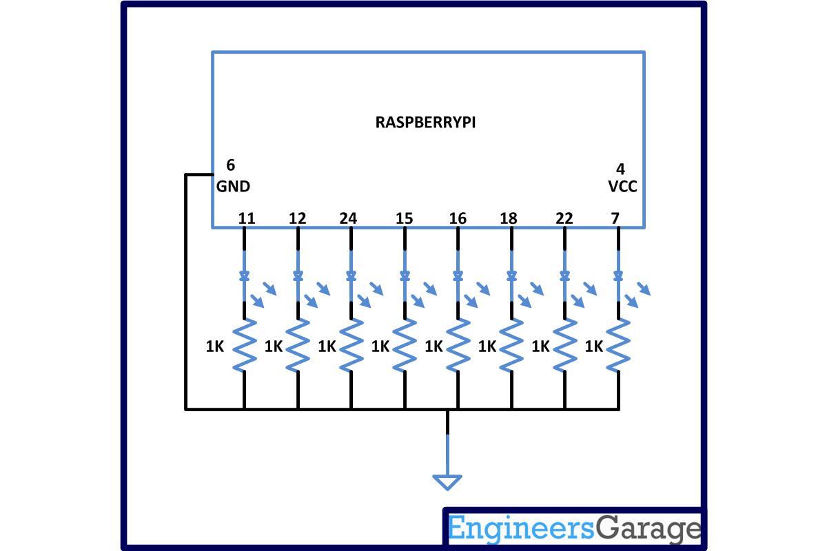 |
Project Components
- LED
- Resistor