SSD1306 is a popular OLED display driver. Portable and wearable devices are the new trends. Small OLED displays are perfect for compact, portable devices. SSD1306 is a single-chip CMOS OLED/PLED driver. It can manage a 128×64 dot matrix graphical display. It is designed to control common cathode OLED panels. The chip has several built-in features such as 256-step brightness control, display RAM, oscillator, and contrast control. These built-in features reduce the external components required and make the chip ready for use with any supported resolution OLED display.
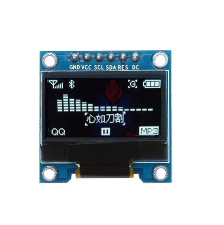
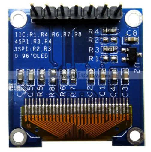
Figure 1. SSD1306 OLED example
SSD1306 is commonly used in monochrome OLED displays with screen resolutions up to 128×64. These displays are now the best alternative to conventional character LCDs. Compared to character LCDs, SSD1306 OLED displays are easy to interact with via I2C or SPI and can display many complex graphics, including text, bitmap images, and animations. Comparing prices, small OLED displays are not much more expensive than character LCDs. Instead, OLED displays are too aesthetic and compact for use in portable and wearable consumer devices. For example, for a smartwatch, character LCDs are not suitable and graphic LCDs are quite more expensive, but a small OLED display is perfect for this.
In this tutorial, we will interface an SSD1306 OLED display with Arduino using the SPI interface. SSD1306 chip-based OLED displays can be connected to a microcontroller or single-board computer using an I2C, SPI or parallel interface. However, I2C and SPI interfaces are more commonly exposed on OLED display modules.
Required components
- Arduino UNO x1
- SSD1306 7-pin OLED Module x1
- Connecting wires or jumper wires
About SSD1306 OLED Display
OLED stands for Organic Light Emitting Diode. OLED displays are similar to LED displays used in televisions and monitors. However, these displays are compact and suitable for use in wearable and portable devices. There are many types of OLED displays. These displays can be classified according to size, color, number of pins and controller IC. OLED displays come in two common sizes – 0.91″ with a 128×32 screen resolution and 0.96″ with a 128×64 resolution. The screen can be monochrome blue, monochrome white or yellow-blue. The OLED display module can have a 3/4-pin port for I2C interface only, or a 7-pin interface for 3-wire SPI, 4-wire SPI and I2C interface. SSD1306 and SSD1331 are the most popular OLED display driver chips. Any OLED display module has the controller chip integrated into the module.
In this project, we are using a 0.96″ OLED display with SSD1306 controller IC. The module has a Yellow-Blue screen with a screen resolution of 128×64. The module used here has a 7-pin interface, allowing the module to be interfaced with any microcontroller or SBC via 3-wire SPI, 4-wire SPI, and I2C interface. The 4-wire SPI interface is the default interface option on the 7-pin module.
How to Interface SSD1306 OLED with Arduino
A 7-pin OLED module offers all interface options such as 3-wire SPI, 4-wire SPI and I2C. 4-wire SPI is the fastest communication mode with OLED and is also the default. The 7-pin OLED display has the following pin configuration.
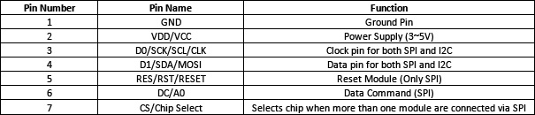
To interface the module with Arduino (or any microcontroller or SBC), connect the GND and VCC/VDD pins to the ground and 5V output of the Arduino, respectively. OLED operates on minimal power, so it does not require any external power supply. It's important to note that OLED doesn't turn on its backlight just by supplying power. No changes to the OLED display are noticeable until it is programmed correctly. D0, D1, RST, DC and CS pins can be connected to any GPIO. A 6-pin module does not have Chip Select.
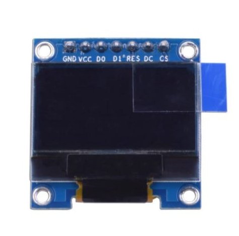
Figure 2. SSD1306 OLED display pin configuration
4-pin OLED modules only offer an I2C interface to communicate with them. It has the following pin configuration.
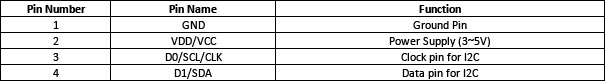
To interface the 4-pin module, connect the GND and VCC pins to ground and 5V output of the Arduino. Connect D0 and D1 pins to any GPIO.
Circuit Connections
In this project, a 7-pin SSD1306 OLED module is connected to Arduino UNO. The module is connected to the Arduino as follows.
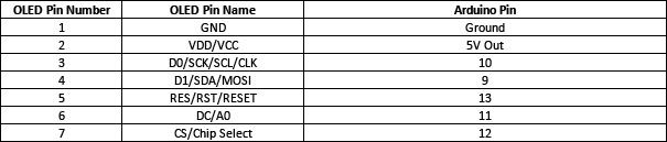
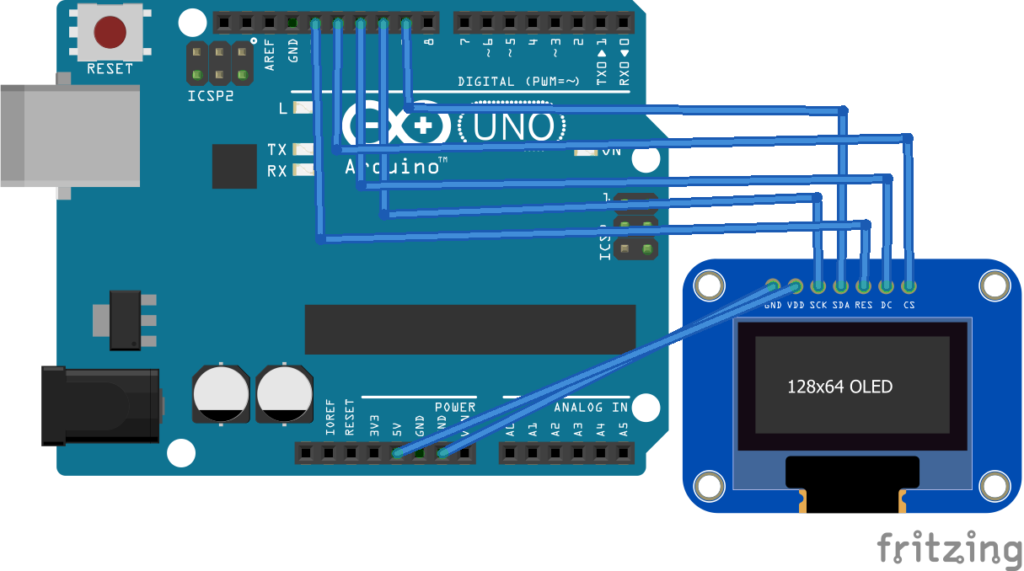
Figure 3 and 4. SSD1306 OLED Screen
Programming SSD1306 OLED display with Arduino
The library for interfacing the SSD1306 with Arduino is available from Adafruit. To find it, navigate to the Arduino IDE's library manager, Sketch -> Add Library -> Manage Libraries. Search for SSD1306 and select the latest version of the Adafruit SSD1306 library. It will also download the GFX library as a dependency.
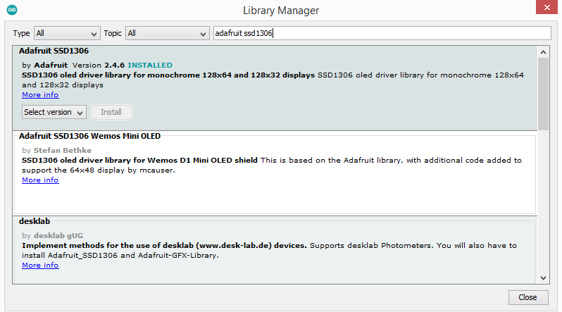
Figure 5. Installing the Adafruit SSD1306 OLED Arduino library
Once included, the library can be imported into code using the following lines:
#include
#include
The library's working examples can now be found under File -> Examples -> Adafruit SSD1306.
The library provides several useful functions. Some of these frequently used functions are listed below.
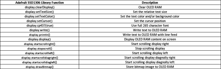
To convert any image to bitmap for display on SSD1306 OLED, you can use the following link.
Arduino Sketch
Result
(Link to P15-DV demonstration video)