The 1-Wire protocol is a proprietary standard for serial data communications from Maxim Integrated. This protocol is a low-speed, half-duplex, bidirectional, low-power master-slave data communications standard used by various devices, including temperature sensors, real-time clocks, EEPROMs, identification devices (intellectual property protection ), timers and iButtons.
There can only be one master device on a standard 1-wire bus, with up to 100 slave devices. Serial communication is fully controlled and managed by the master device. The protocol does not use a clock signal and data is communicated at fixed time intervals. This means that slave devices must synchronize with the master for read and write operations.
The standard 1-wire bus has a minimum of two wires: a data line and the ground return. Most 1-wire devices have three terminals. The third line is added for a positive offer.
For a two-line bus, the VDD and GND terminals of the 1-wire slave are connected to the ground return. The signal and data are provided by the data line. This is called parasitic feeding mode.
For a bus with three lines, the VDD is also assigned to the positive feed. This is called conventional eating. The mode is considered more reliable than parasitic power because the latter depends on the pull-up time on the data line.
Some 1-wire devices have five terminals for greater line access for sequence detection.
As 1-Wire is a proprietary protocol, it has no hardware implementation on microcontrollers. However, it is implemented in the software of most microcontrollers and single-board computers due to the popularity of 1-wire devices – such as iButtons.
MicroPython implements the 1-Wire protocol in its software, using bit-banging. The pattern can be applied to any pin with output capability. In this article, we will cover the MicroPython Onewire driver, discussing how it can be used to interface with a DS18B20 temperature sensor.
The protocol
For the 1-Wire protocol, data communication with slave devices is controlled by the master. Since there is no clock signal, slaves must synchronize their internal clock with signals from the master device. The master can be a microcontroller, microcomputer or desktop computer.
The master uses five types of signals to communicate with slave devices: Reset, Presence, Write 0, Write 1 and Read.
The master starts communication with the slaves with a reset signal. In response, the slaves will pull the data line, which will be sampled by the master as a presence signal. Once the presence of at least one slave on the bus is confirmed, the master starts sending ROM commands.
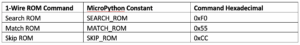
The first command is the search ROM command, which searches for the ROM addresses of the connected slaves. Each 1-wire slave is identified by a 64-bit ROM address. When the master receives the ROM addresses of the connected slaves, it looks for address conflicts. The addresses are further used by the master device to identify a 1-wire device and communicate the function commands associated with it.
ROM commands are 8 bits long. All data, whether written or read from slave devices, is also in groups of 8 bits.
By default, the data line is raised with the help of an external pull-up resistor. Without this pull-up, data communication would not be possible.
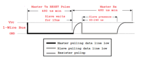
Reset is the first signal sent by the master. This is done by pulling the data line to 480 nodes. It then releases the data line, allowing the pull-up resistor to pull the data line up.
Slave devices have a basic monostable multivibrator to detect the state of the data line and the duration of the pulses. When connected to the bus, slaves can detect a reset signal and respond by pulling the data line down for 60~240 knots.
- If, after a reset signal, the data line is still high, the master assumes that no slaves are connected to the bus.
- If, after a reset signal, the data line is reduced, the master recognizes that at least one slave is connected to the bus.

After confirming the presence of a 1-wire slave, the master starts writing ROM and function commands. In response to these commands, the master will read the slave devices. As mentioned, commands and data are in groups of 8 bits. They are communicated as packets where errors in each 8-bit block are reviewed with a cyclic redundancy check (CRC).
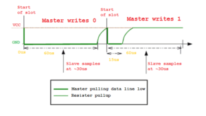
At the signal level, each bit is communicated in a fixed time interval of 60 us or less if the bus is overloaded. There is a 1us interval between each time interval, so the pull-up resistor can pull the data line up between each bit's communication.
- To write '0', the master pulls the data line down for the entire 60 us time interval and then releases it for the 1 us interval between time intervals.
- To write '1', the master pulls the data line down for 15 knots and then releases it for a 1us interval between time steps.
- The slaves sample bits from the master after 30 nodes of each time slot.
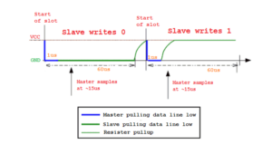
At this point, the master reads the slave again, little by little. Slave data continues to be communicated in groups of 8 bits. The master drops the data line by 1 us and releases it, and then samples the data from the bus after 15 us.
- If the slave writes '0' to the bus, it will keep the line suspended for the entire 60 us time interval. It then flushes the data line for a 1us interval between time steps.
- If the slave writes '1' to the bus, it will keep the line disconnected for 15 nodes. It then releases the data line so that the pull-up resistor pulls the data line up.
- The master samples data after 15 nodes of each time step.
This is how the master communicates the reset and presence signals, writes 1, writes 0 and reads the signals with the 1-wire slaves. The protocol is implemented by microcontrollers and computers using bit-banging or the universal asynchronous receiver-transmitter (UART).
Learn more about the 1-Wire protocol here .
MicroPython Onewire Driver
MicroPython implements the Onewire driver as a library package, which is now part of the standard MicroPython firmware. The library is called single-thread . It can be imported into a MicroPython script using this instruction:
import a thread
The single-wire driver includes two libraries: new and ds18x20 . The Onewire class is a generic implementation of the 1-Wire protocol. The ds18x20 is a specific implementation of the temperature reading protocol of 1-wire digital thermometers such as the DS18B20 and DS18S20.
These libraries can be accessed using these instructions:
import a thread
import ds18x20
import onewire, ds18x20
The Onewire The driver depends on MicroPython firmware time and machine modules. Three constants are used for the ROM commands, listed below.
The driver's Onewire class is instantiated with a constructor function. The builder has this prototype:
OneWire (pin)
The constructor method takes only a single argument (i.e. the pin where the 1-Wire protocol is implemented). A pin passed as an argument must have output capability.
The other methods provided by Onewire class are as follows:
- restart : sends the restart signal. If any 1-wire slave is detected, it will return True. Otherwise, it returns False. This method does not accept any arguments.
- read bit : reads a bit of the data line. No arguments needed. It returns a Boolean value, which is True if the read bit is '1' or False if the read bit is '0'.
- readingbyte : reads a byte from the data line. It calls the read_bit method eight times and stores each bit in a byte object. The byte is returned by the method.
- read in (count) : reads the specified number of bytes from the data line. It iterates the read_byte method for the number of times specified as an argument. The bytes are stored in a buffer object, which is returned by the method.
- write bit (value) : Writes a bit, '0' or '1,' to the data line. A Boolean argument is required.
- writebyte(value) : writes a byte to the data line. It takes a byte object as an argument.
- write (buf) : writes a group of bytes to the data line. It takes a buffer object as an argument. All bytes stored in the buffer object are written to the data line.
- select_rom(rom) : selects a specific 1-thread slave to talk to. The slave is identified by its 64-bit address. This method takes an 8-byte bytearray as an argument. The bytearray is called a ROM object.
- crc8 (data) : Used to perform a cyclic redundancy check on data. It takes a buffer object as an argument.
- Scan : Used to scan 1-wire slaves connected to the bus. It returns a list of ROM addresses for all attached slaves. Each ROM address is an 8-byte bytearray.
- _search_rom(l_rom, difference) : Used to detect ROM addresses by checking whether each one is a valid 64-bit ROM address or not. It's called the inside scan method, used to search for connected 1-wire devices.
The ds18x20 library was written especially to obtain temperature readings from DS18B20 and DS18S20 digital thermometers. The library makes use of the const class from the MicroPython library.
The following three constants for DS18X20 function commands are used by the library.
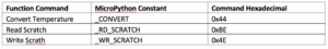
The DS18X20 class is instantiated using a constructor function. The builder has this prototype:
DS18X20 (one wire)
The constructor takes a one-threaded object as an argument. The other methods provided by the DS18X20 class include:
- Scan : Used to scan the 1-wire temperature sensor connected to the bus. It reads the ROM addresses of connected 1-wire devices, checking whether any addresses begin with 0x10, 0x22, or 0x28. The first 8 bits of the ROM address are a family code: 0x10 is the family code for the DS18S20, 0x22 is the family code for the DS1922, and 0x28 is the family code for the DS18B20.
- read_scratch : reads the contents of the DS18x20 scratchpad. The least significant bit is read first up to the ninth byte. The ninth byte is the CRC byte.
- write_scratch : writes three bytes of data to the DS18x20 scratchpad. The least significant bit is sent first. The first byte is written to the TH register, the second bit to the TL register, and the third bit to the configuration register.
- convert_temp(rom=None) : Sends the function command to start temperature conversion to a connected DS18X20 device. This method returns nothing. Instead, it launches the DS18X20 device to begin temperature conversion. This method does not allow you to select a specific 1-wire temperature sensor. DS18x20 sensors connected to the 1-wire bus are commanded to start temperature conversion.
- read_temp (rom=None) : Reads the temperature of the specified DS18X20 device once the conversion is complete. Otherwise, it returns nothing. The specific DS18x20 sensor is selected by passing the ROM address as an argument. If the ROM address is not passed, any DS18x20 sensor connected to a 1-wire bus will be automatically selected.
The libraries and classes discussed here are part of the official MicroPython framework. There are also some board specific drivers for 1-wire and DS18x20 thermometers. These drivers must be loaded on the respective board.
These card-specific drivers may have different or additional class methods, such as for converting the raw temperature reading to degrees Celsius. The Onewire driver in the official MicroPython framework can be browsed in the micropython-xxx\drivers\onewire folder.
MicroPython Onewire Driver on ESP8266 and ESP32
MicroPython's Onewire driver works on all pins of the ESP8266 and ESP32. Here is an example:
Machine Import Pin
import a thread
ow = onewire.OneWire(Pin(12))
ai.scan
ow.reset
ow.readbyte
ai.writebyte(0x12)
ai.write('123')
ow.select_rom(b'12345678′)
A valid example using the ds18x20 library:
import time, ds18x20
ds = ds18x20.DS18X20(ow)
roms = ds.scan
ds.convert_temp
hour.sleep_ms(750)
for rom in roms:
print(ds.read_temp(rom))
DS18B20 temperature sensor
DS18B20 is a 1-wire digital thermometer from Maxim Integrated. The sensor has multidrop capability, allowing multiple DS18B20 sensors to be interfaced on a single data line as a distributed network. It produces a temperature measurement with resolution scales of 9 to 12 bits. The operating temperature range of the DS18B20 is -55˚ to 125˚ C with an accuracy of +/-0.5˚ C. The default sensor resolution is 12 bits, which measures temperature with an accuracy of 0.0625 W.
The sensor takes less than 750 ms to convert a reading. Therefore, it is possible to obtain temperature measurements at one-second intervals from the sensor network.
The operating voltage of DS18B20 is 3.3~5V and the current consumption is about 1mA. This temperature sensor can easily interface with any microcontroller or microcomputer as long as a software library for the 1-Wire protocol is available.
The sensor comes in two types of packaging and one is waterproof.
The DS18B20 has this pin diagram:
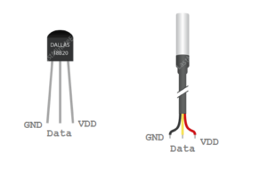 In the waterproof version of the sensor,
The pins are identified by waterproof sensor color coding. The GND, CDD and D data lines are black, red and yellow wires.
Preparing ESP8266 and ESP32
The MicroPython IDE must be ready to write, edit, and upload code. You can also use uPyCraft IDE or Thonny IDE for the software. With the help of respective IDE, upload MicroPython firmware for ESP8266 or ESP32. Learn how to prepare uPyCraft IDE and upload MicroPython firmware for ESP8266/ESP32 .
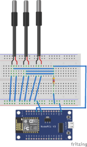
DS18B20 interface with ESP8266
The DS18B20 can be connected to the ESP8266 in parasitic or conventional power mode. For parasitic power mode, connect the output pin of the DS18B20 to any of the GPIOs of the ESP8266.
Below, the output pin is connected to GPIO4. Remove the data from the high pin by connecting it to the 3V pin of the ESP8266 through the 4.7K resistor. Connect the GND and VDD pins of the DS18B20 to the ground of the ESP8266.
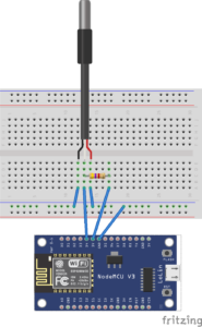
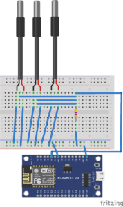
For conventional power mode, connect VDD pin of DS18B20 to 3V instead of GND.

DS18B20 interface with ESP32
The DS18B20 can be interfaced with the ESP32 in parasitic or conventional power mode. For parasitic power mode, the VDD and GND of the DS18B20 are connected to ground. The data output pin of the DS18B20 connects to any of the GPIOs of the ESP32 with high voltage via the 4.7K resistor.
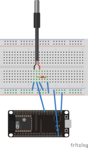
For conventional power, connect VDD of DS18B20 to ESP32 instead of ground.

MicroPython Script
import machine, onewire, ds18x20, time
ds = ds18x20.DS18X20(onewire.OneWire(machine.Pin(4)))
roms = ds.scan
print('DS devices found: ', roms)
while True:
ds.convert_temp
hour.sleep_ms(750)
for rom in roms:
print (rom)
print(ds.read_temp(rom))
Results
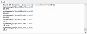
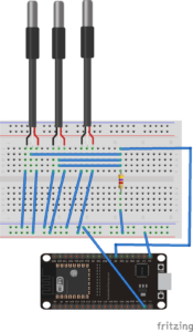
Interfacing multiple DS18B20 with ESP8266
Many DS18B20 sensors can be connected to the same 1 wire. The MicroPython library can read temperatures from all connected sensors simultaneously.
For parasitic power mode, make the same circuit connections shown below.
Conventional power mode is recommended when multiple DS18B20s are connected to the 1-wire bus. For conventional power mode, make circuit connections as shown below.
Interfacing multiple DS18B20 with ESP32
Multiple DS18B20 sensors can be connected to the ESP32. For parasitic power mode, make the circuit connections shown below.
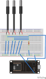
For conventional power mode, make the circuit connections shown below.
MicroPython Script
import machine, onewire, ds18x20, time
ds = ds18x20.DS18X20(onewire.OneWire(machine.Pin(4)))
roms = ds.scan
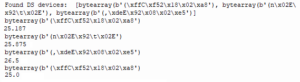
print('DS devices found: ', roms)
while True:
ds.convert_temp
hour.sleep_ms(750)
for rom in roms:
print (rom)
print(ds.read_temp(rom))
sleeptime(5)
Results
Conclusion
MicroPython has a well-written driver for 1-wire devices and a separate driver for DS18BX20 devices – which works with DS18B20, DS1922 and DS18S20.
It is easy to interface DS18X20 digital thermometers with ESP8266 and ESP32. Multiple DS18X20 devices can be connected to the same 1-wire bus without any problems. The same MicroPython code works for single and multiple DS18X20 thermometers.