In Part I of this series, we demonstrated how to display data from analog (value) sensors, such as POT or LM35, on a TFT LCD. A TFT is a thin-film transistor display (typically a television screen or computer monitor) of much higher quality than a normal LCD display.
In this article, we will explain how to display temperature, humidity and soil moisture on a TFT LCD. We will use a digital humidity and temperature (DHT) sensor for measurement. It is a smart sensor that detects ambient temperature and humidity and provides digital readings and value outputs. The Arduino will then obtain these digital values from the sensor and display them on the TFT LCD.
The soil moisture sensor we chose is also an analog sensor. It provides a 0 to 5 V analog voltage output as the moisture changes in the soil. The Arduino will read the analog voltage and convert it to a digital value for display.
Ultimately, the three parameters – temperature, humidity and soil moisture – are displayed simultaneously on the TFT LCD.
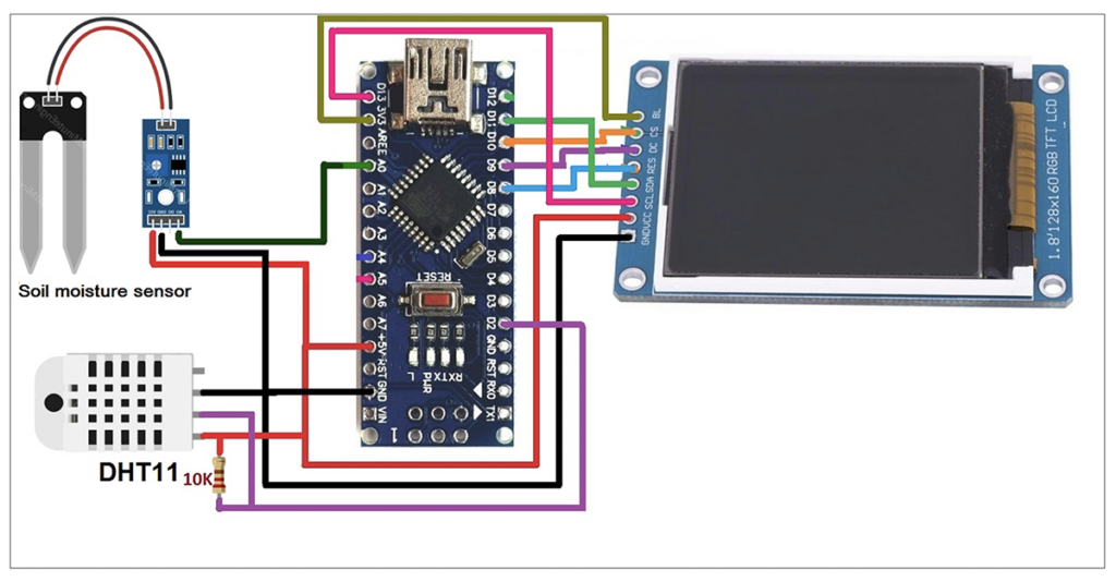
The circuit diagram of displaying sensor value (data) on a TFT LCD using Arduino. The circuit consists of four components including the soil moisture sensor, DHT11, an Arduino NANO board and a TFT LCD.
Circuit Connections
The soil moisture sensor has three interface pins: VCC, GND and A0. Arduino provides the VCC pin with 5V. The GND pin connects to common ground. Pin A0 is the analog voltage of the sensor output pin. It connects to the A0 pin of the Arduino.
The DHT11 also has three interface pins: VCC, GND and OP. Arduino provides the VCC pin with 5V. The GND pin connects to common ground. The OP pin connects to the Arduino's D2 pin. The 10K pull-up resistor connects to the VCC and OP pins (as shown).
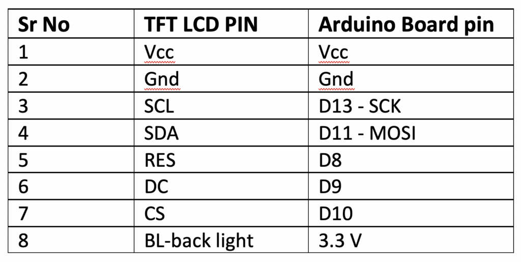
The TFT LCD has eight pins in total and works on the SPI protocol. Its pins connect to the Arduino's SPI pins.
The circuit is fully powered by the Arduino 5V power output. The Arduino receives power from a computer's USB port, so no additional power supply is required.
Circuit operation
The soil moisture sensor probe detects the moisture content of the soil. If there is an increase in moisture content, its strength decreases. The sensor module provides an analog voltage output corresponding to any change in this resistance (which reflects a change in soil moisture).
This analog voltage output is read by the Arduino and converted to a digital value from 0 to 1023, and then to a percentage between 0 to 100% and an integer. Then it is converted to a string and then to a character array because TFT LCD can only display characters.
The DHT sensor provides direct digital values of ambient humidity and temperature. Both values are also converted to a string and then to a character array.
All three values are displayed on the TFT LCD as:
- Temperature in o C
- Humidity in % RH (relative humidity)
- Humidity in %.
Again, values are displayed as characters on the TFT LCD.
Arduino has a TFT library (“TFT.h”), which is used together with two other libraries (“SPI.h” and “wire.h”).
The Arduino TFT library has direct functions to display TEXT, graphics, images, etc. It can also display multiple colors on the TFT LCD. Since the TFT LCD works on an SPI, an SPI and wire library are also required.
Software program
An overview of the circuit…
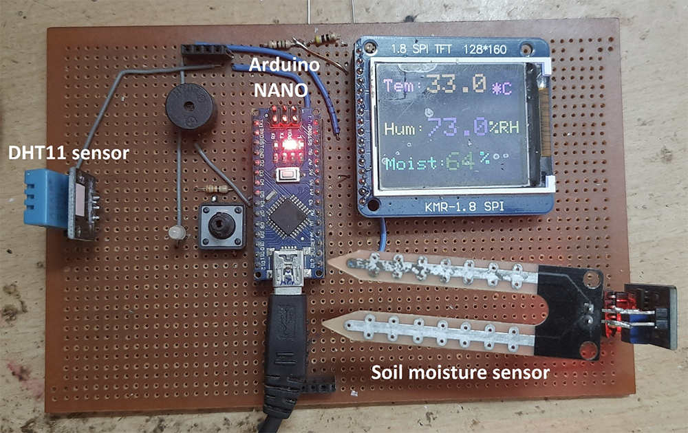
A prototype display showing temperature, humidity and soil moisture using the DHT11 and soil moisture sensor.
A YouTube video link for this article is available here.
In the next article in this tutorial series, we will learn how to measure and display distance on a TFT LCD using the UDM sensor, HC SR04.