Voltage and current sources are two fundamental types of electrical sources used in electronic circuits. A voltage source, such as a battery, is commonly used in many devices. It is a two-terminal device that maintains a constant voltage across its terminals regardless of the current flowing through the source.
A current source is typically less discussed and more difficult and expensive to design. It is also a two-terminal device, but it maintains a constant current through its terminals, regardless of the voltage at the source. This means it is used to ensure a constant current even if the load fluctuates.
In this experiment, we will design a constant current source application using a linear buck regulator.
Specifications
- The LM338 Buck linear regulator
- Input voltage range – 1.2 to 32V
- Maximum output current – 5A
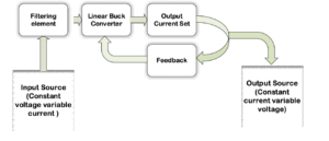
Block diagram

Block diagram of a constant current source using a linear buck converter.

Circuit Diagram

Circuit diagram of a constant current source using LM338.
Principle
When using any linear regulator as a current source, the circuit works on the principle of a feedback circuit.
The regulator consists of a feedback pin (the tuning pin) that returns output to the regulator and maintains a fixed voltage in the feedback network. This network is a resistor, which determines the output current at the output.
Circuit design
Here are the steps for circuit design.
1. Input source – 24V DC
2. Linear buck converter – CI LM338
LM338 Features
- Overload protection – in the event of an overload, the device will reduce its output current until the overload is removed
- Thermal regulation
- Output short circuit protection
3. Output current set – the output current is based on the feedback network, which is the resistor
The equation to calculate the feedback resistor…
Applying Ohm's famous law, we obtain:  . V reference = regulator voltage reference
LM338 regulator, V reference =1.25 V
Desired constant output current, I out = 4A
Feedback resistor, R Facebook =V reference / EU out
R Facebook = 1.25/5
R Facebook = 0.33E
4. Feedback resistor power rating
The equation to calculate the nominal power of the resistor…
P R = me 2 *R Facebook
P R = (4*4)*0.33
P R = 5.28W (minimum)
5. Filtering – t The capacitor, which is at the input, grounds all the ripples and peaks of the source. To reduce the total ESR, we can connect a ceramic capacitor along with an electrolyte.
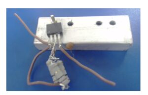
6. Cooling system – the heat sink must be assembled with the regulator because we are consuming a large amount of current. This will produce a lot of heat on the surface of the IC and may ignite it. Therefore, it is important to use a fan or heatsink to reduce its temperature.
How the circuit works
In our constant current source, the feedback circuit maintains a fixed output voltage across the feedback resistor. According to Ohm's law, with a fixed value of voltage and a resistor, a constant amount of current will flow.
This will generate a constant current at the output, regardless of the load.
Output current regulation
All current sources provide a regulated current, but only for a specific load range.
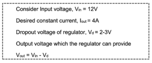
It is possible to calculate the load limit of the linear regulator using the following equation…

V out = 12 – 3
V out = 9V…………………………Eq.2

V R = 5*4.7
V R = 23.5 V
The regulator is not capable of providing 23.5 V at the output. Therefore, we must first calculate the output load limit using the equation below…

The maximum value of the resistive load, R i = 2.25E
Test results
Initially, we design the current source for 5A as the IC is rated for 5A output current. However, the IC was unable to maintain a constant output current of 5A and started decreasing in value even with heatsink and cooling fan.
This may be due to the IC's internal thermal regulation, which tries to maintain its temperature and decreases current if it is in a high power dissipation state.
So instead we tested the circuit using a current of 3.7A and it worked perfectly with the heatsink.
Observation

The output current begins to stabilize with a load of 1 Ohm. The difference in output current is due to the resistor tolerance values.
Circuit limitations
- Input Source – A high voltage input source is required to increase the maximum load limit
- Cost – A high power feedback resistor increases the cost
- Efficiency – There is less efficiency due to high power dissipation through the feedback resistor
Thermal management
For extra heat dissipation, heat is connected to the IC. You can also use a fan to disperse the hot air.
Forms
- Battery charging
- On transistor bias
- Lighting systems
- Regulated supply
Precautions
- Make sure the power rating of the feedback resistor is in accordance with the product requirements.
- Always place a load below the limits of the current source.
- A capacitor must be connected between the input pin and ground to regulate the DC input voltage.
- The circuit capacitor must have a higher rated voltage than the input supply voltage. Otherwise, the capacitor will leak current due to excess voltage on its plates and burst.
- Make sure all capacitors are discharged before working on a DC power supply.
- Do not supply an input voltage higher than the operating input voltage range.
- Always connect a heat sink or fan for heat dissipation around the IC.

Video

