
As its name suggests, wide area network or LoRaWAN technology is widely used for long-range, low-power communication in Internet of Things (IoT) applications.
In this article, we will guide you through the process of connecting an SX130x 868M LoRaWAN gateway module to a Raspberry Pi 4 using hardware attached on top (HAT). This configuration creates a LoRaWAN gateway, allowing the Raspberry Pi (RPi) to communicate with LoRaWAN-enabled devices.
What is necessary
- Raspberry Pi 4 (model B or higher is recommended) – link
- The SX130x 868M LoRaWAN gateway module – link
- A LoRa antenna compatible with the module – and comes with SX1302
- A MicroSD card with Raspbian OS installed (instructions below) – 32 GB
- An SD card reader
- Power supply for Raspberry Pi – Link
- An Internet connection
Step 1. Gather the hardware
Before you begin, you will need all the necessary hardware components, including a Raspberry Pi 4, the SX130x 868M LoRaWAN gateway module, a LoRa antenna, and a working MicroSD card with Raspbian operating system.
Step 2. Assemble the hardware
Insert the MicroSD card into the Raspberry Pi (after installing the RPi — see Step 3 for instructions)
Connect the SX130x LoRaWAN gateway module to the GPIO pins of the Raspberry Pi. Make sure the pins are properly aligned and the module is securely connected. It's a hat, so it should fit perfectly.

Figure 1. The hardware assembled between the SX130x LoRaWAN gateway module and the GPIO pins of the Raspberry Pi.
Step 3. Install Raspberry Pi with OS
Install Raspberry Pi Imager software using this link to download the software for installation on Windows.
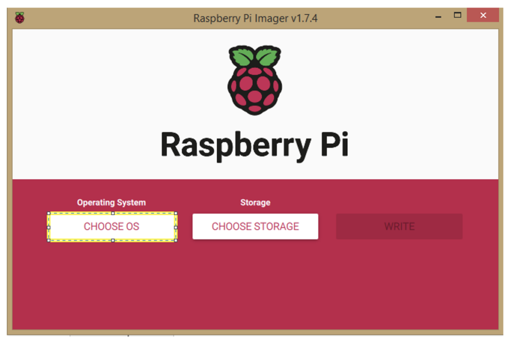
Figure 2. The Raspberry Pi Imager software
Click on “CHOOSE OS”.
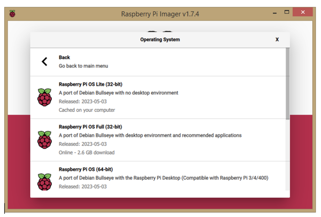
Figure 3. Select 'OS' in the Imager software.
Choose OS Lite (32-bit) version and then choose Storage Device option in the next step.
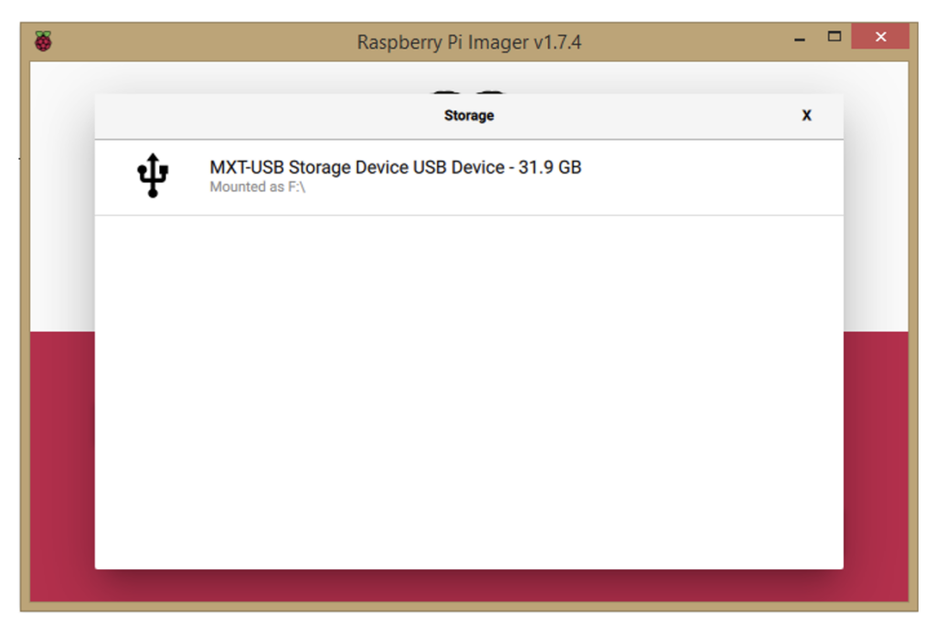
Figure 4. Select the Storage Device option.
Then insert the SD card into the computer using the SD card reader. Select the displayed SD card. Make sure you click the gear icon before clicking the 'Compose' button.
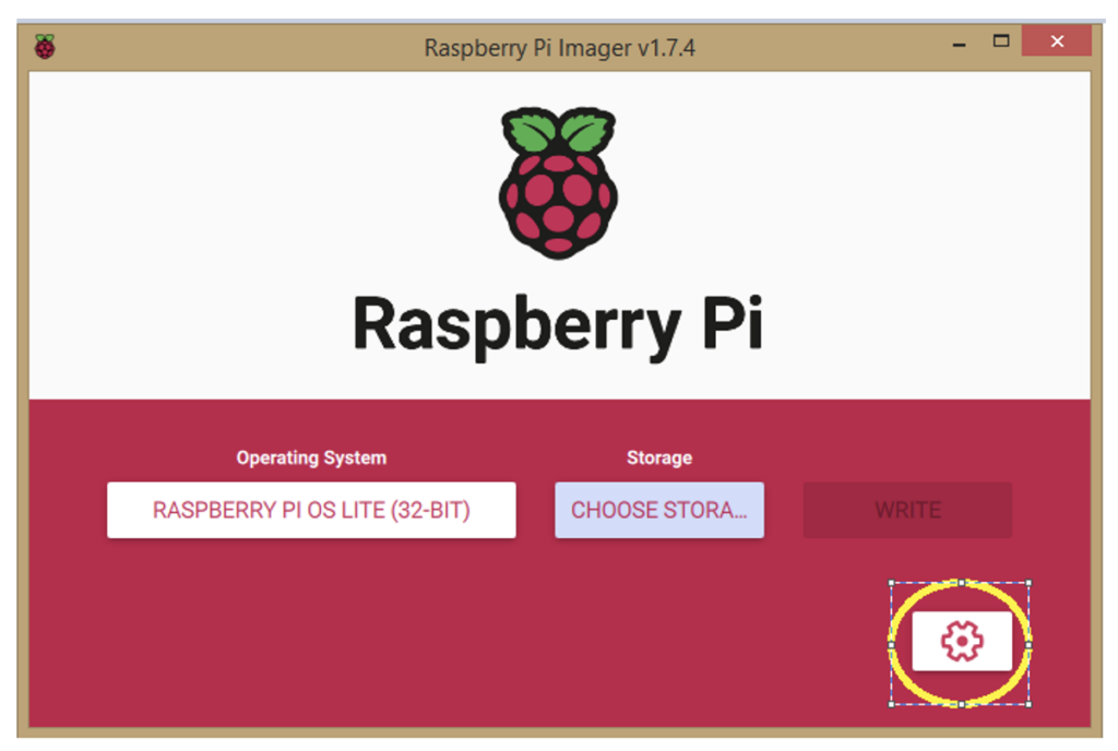
Figure 5. Use the gear button to change the Wi-Fi setting and other options. Then click on the 'Write' image.
Now, change the settings for Wi-Fi and other options. Then click 'Enable SSH' and set your username and password. Click 'Set up Wireless LAN' and enter your Wi-Fi SSID and password. This allows the RPi to boot without connecting it to a desktop display.
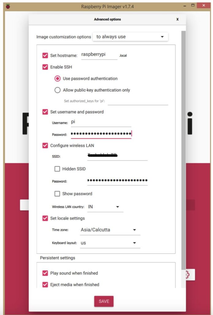
Figure 6. Add your Wi-Fi SSID and password.
Click on the 'Save' buttons and then the 'Write' buttons. Wait for the process to complete and when done, remove the SD card from your current device and insert it into the Raspberry Pi.
Step 4. Connect Raspberry Pi using SSH
After mounting and inserting the SD card, turn on the Raspberry Pi. Follow the instructions below to establish an SSH connection.
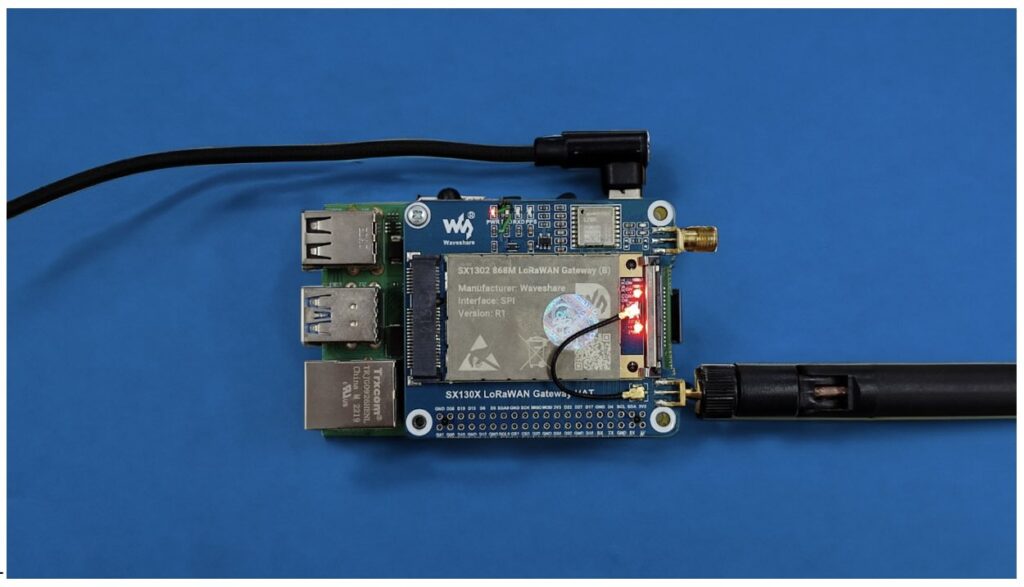
Figure 7. Power turns on after connecting the RPi using SSH.
Determining the RPi's IP address is necessary to establish a connection. To do this, download Angry IP Scanner: link
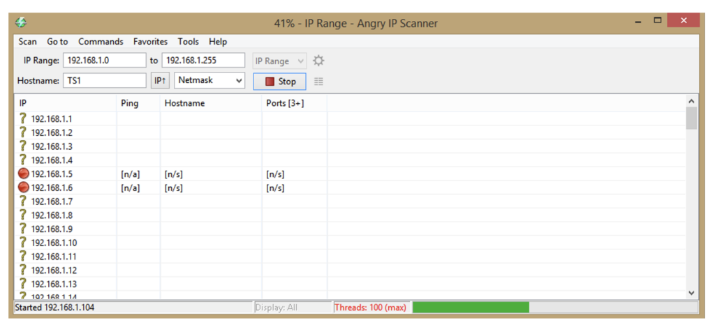
Figure 8. The angry IP software.
After clicking 'Start', the screen below will appear. Once the process is complete, locate the IP address with the hostname “Raspberry pi.” You can also find the appropriate information in the DHCP section of your router's configuration page.
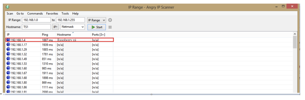
Figure 9. The IP scanning process.
In our case, the IP address is 192.168.1.4. However, in your case it will be different. Then download bitvise ssh software : link
Launch the software and log in to the IP address using the username and password defined during the SD card update process.
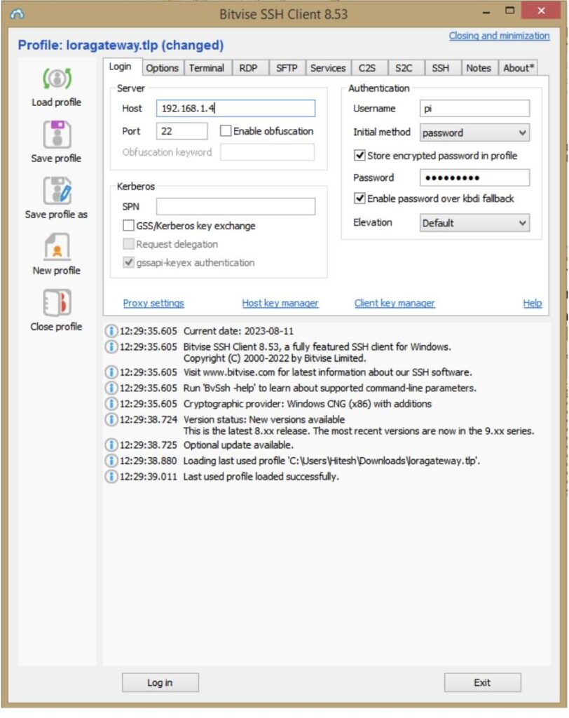
Figure 10. The process of moving SSH to RPi.
Click 'New Terminal Console'.
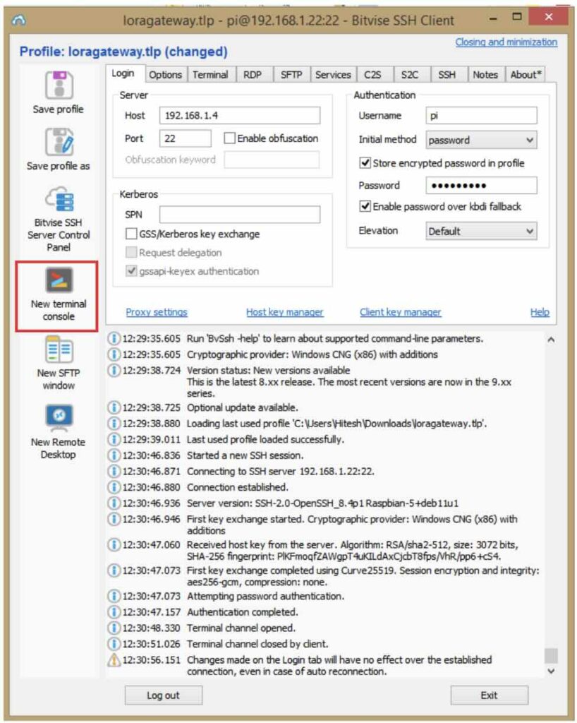
Figure 11. Click 'New Terminal Console'.
Afterwards, you will see the following screen.
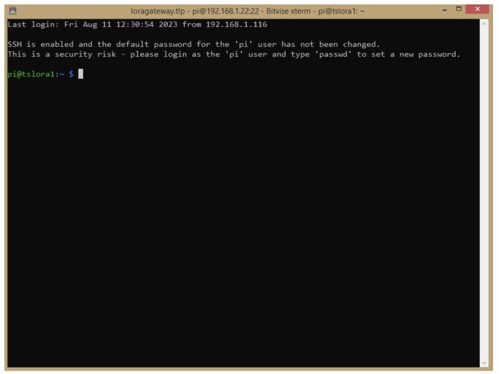
Figure 12. The 'Terminal' screen after login.
We have successfully established an SSH connection with Raspberry Pi.
Step 5. Configure RPi
Enable SPI, Serial and I2C using this command: “Raspi-config”
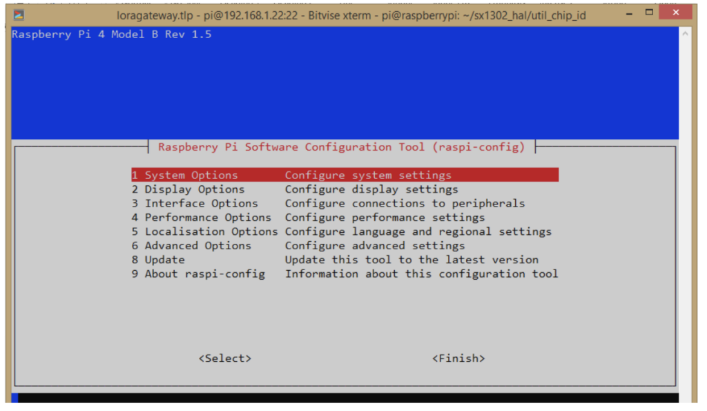
Figure 13. The 'System Options' window for configuring the RPi.
Go to 'System Options' and enable SPI, Serial and I2C.
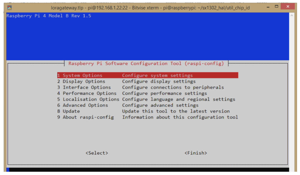
Figure 14. Configure the RPi by enabling SPI, I2C and Serial in the interface window.
Click “Yes”.
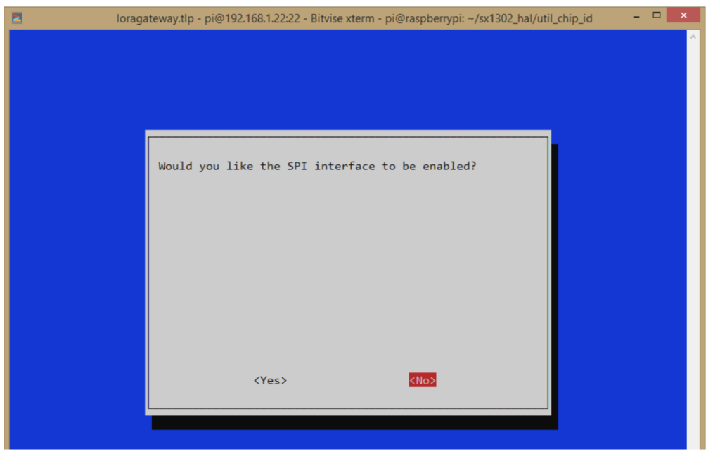
Figure 15. Click 'Yes' for all three options.
Then it will ask to restart.
Step 6. Connecting SX1302
Install the SX1302 binaries for the gateway by following these steps:
- sudo apt update
- sudo apt install git
- CD
- git clone
- cd sx1302_hal
- clean all
- do everything
- tools cp/reset_lgw.sh util_chip_id/
- cp tools/reset_lgw.sh packet_forwarder/
Next, you need to check if the hardware is connected correctly.
- CD sx1302_hal/util_chip_id/- ./chip_id
Once there is a connection established with the hardware, you will see output similar to this…
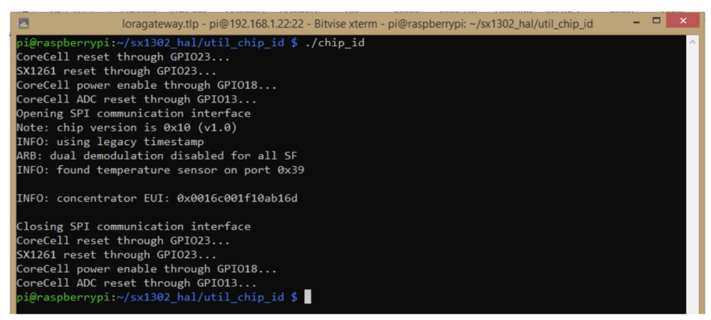
Figure 16. The 'Get Chip ID' command.
Your EUI ID is the MAC address of the gateway, so be sure to write it down. Start the LoRa concentrator shield using this command, providing any configuration file from the folder.
- cd sx1302_hal/packet_forwarder/-
- ./lora_pkt_fwd -c global_conf.json.sx1250.EU868
A successful connection to the LoRa hub will look like this:
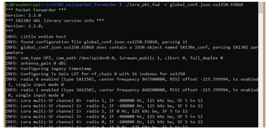
Figure 17. The gateway is active and a connection has been successfully established with the LoRa hub
At this point, all data sent by the EU868 profile will be received by this screen.
Conclusion
Sending data through this gateway will allow data to be received. The next step involves connecting, configuring, and managing the gateway using Chirpstack.


