A polygraph is an instrument that records physiological indicators such as pulse rate, blood pressure and electrodermal activity of a human subject questioned by an operator. It is commonly called a lie detector test because it is designed to assess whether a person is telling the truth.
Industry standard polygraph equipment is said to be 80 to 90% accurate if used correctly with proper quality controls. They are not foolproof, but these devices have been used in investigations.
An important physiological measurement is a person's electrodermal activity, which consists of changes in the skin such as sweating (which can be an indication of lying for some people). It is simple to design polygraph equipment based on electrodermal activity, and this type of “lie detector” can be built using Arduino or any microcontroller for fun.
Microcontroller boards have one or more analog inputs and one of them can be used to measure skin conductance. The electrical conductance can then be plotted as a graph via the Arduino Serial Plotter.
For the most part, the electrical conductance graph of a typical person is consistent. When someone lies, the person becomes nervous, which can result in a change in the electrical conductance of the skin. This is a potential indication that the subject is lying to the question.
In this project we will build a type of lie detector based on electrodermal activity using Arduino UNO.
Components
1. Arduino UNO x1
2. Red LED x1
3. Yellow LED x1
4. Green LED x1
5. 330Ω x3 resistors
6. Resistance 2K x1
7. Jumper Wires
8. Electrical wires
9. Arduino USB Cable
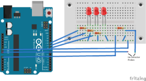
Circuit Connections
- Connect the red LED anode to the Arduino's GPIO10 through the 330Ω resistor
- Connect the anodes of the yellow and green LEDs to the Arduino's GPIO9 and GPIO8, respectively, through the 330Ω resistors
- Connect the cathodes of all resistors to the Arduino ground
- Connect a jumper wire to the Arduino analog input A0 and pull it to the Arduino ground through the 2K resistor
- Extend the A0 pin connection to an electrical wire
- Extend a 5V electrical wire from Arduino
The extended electrical wires from pin A0 and the 5V output will act as probes for our lie detector. The ends of the probe can be fixed to pieces of aluminum foil, secured by adhesive tape, to ensure uninterrupted contact with the subject's fingers.
During prototyping, the open ends of electrical wires can also be secured to the subject's fingers using electrical tape.

Arduino Sketch
//Arduino Lie Detector
empty configuration {
Serial.begin(9600);
pinMode(10, OUTPUT);
pinMode(9, OUTPUT);
pinMode(8, OUTPUT);
digitalWrite(10, HIGH);
delay(500);
digitalWrite(9, HIGH);
delay(500);
digitalWrite(8, HIGH);
delay(500);
}
empty loop {
if (analogRead(A0) > 900)
{
digitalWrite(8, HIGH);
}
other
{
digitalWrite(8, DOWN);
}
if (analogRead(A0) > 300)
{
digitalWrite(9, HIGH);
}
other
{
digitalWrite(9, DOWN);
}
if (analogRead(A0) > 600)
{
digitalWrite(10, HIGH);
}
other
{
digitalWrite(10, DOWN);
}
Serial.println(analogRead(A0));
delay(20);
}
How it works
Once the circuit connections are complete, load the sketch into the Arduino UNO and connect the open ends of the probes to the subject's fingertips. Open the Arduino Serial Plotter and start observing the electrical conductance graph.
Initially the graph is consistent, with periodic variations in the analog input read. Then start questioning the subject. First, ask simple questions that you know to be true, like 'What's your name?'; 'What city do you live in?'; 'How old are you?'
Normally, the graph on Arduino serial plotter remains consistent without any deviations. Slowly ask new questions, including ones the subject might lie about (you can ask them to do this for fun!).
Depending on the subject, you may notice a change in the graph. This may be an indication that the subject is lying.
Over the course of a long investigation, threshold values of the analog input can be determined, which can indicate when the subject is lying or telling the truth. Values can then be added to the sketch to light up the red LED when it detects a “lie” and the green LED when it detects the “truth”.
The code
The Arduino sketch monitors analog input from the skin of the subject's fingertips. Analog readings are plotted as a graph in the Serial Plotter. The plotted graph is observed for a long time to determine the physiological behavior of the subject. Threshold values are defined in the sketch for lie detection respectively. These values are also used to light up LEDs as truth or lie indicators.
The results
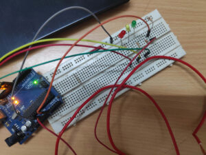
An Arduino lie detector based on electrodermal activity built on a prototyping board…
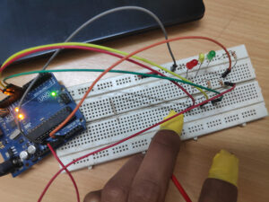
The subject's fingertips are connected to the probes using electrical tape during prototyping, as shown here...
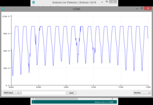
A normal plot for a subject during an initial investigation, as observed on the Serial Plotter...
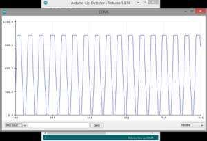 During a period of questioning, the subject lied several times as seen by the abrupt changes in the graph below…