Brain waves to control a device using relay motor
SUMMARY
So far in the brainwave series, we have carried out experiments such as GSM and alarm speaker. Now let's try harder and move on to more real-time applications. It will be a good check on the reliability of the brainwave module.
In this article, I am planning some real-time applications on Brain Wave, including home automation. This time I tried to control a device using a relay. Relay is just a switching device through which we can drive AC and DC appliances. Although it also depends on the maximum current that the relay can trigger and the total current that our device needs. I believe it will be good to control household appliances just by thinking and having a higher level of concentration. So let's see more details about this.

Fig. 1: Image showing home appliances controlled by brain waves
DESCRIPTION
As you know that we are getting the values of all types of brain waves from our Arduino, our task here is just to find the wave that is most affected by alertness or concentration. Alpha waves show us many variations depending on our state of alert. So, first we check the alpha wave values at different alert levels. I tried my level of meditation and then recorded them for testing purposes. While testing on myself, I found that alpha wave values cross 3 Lacs only when my concentration is highest. So I set the coding level to 3 Lacs on my Arduino . We found that the alpha wave values of mindflex range from 1 Lac to 10 Lacs and hence we set a level at 3 Lacs. Whenever the values were greater than that, we activated the relay.

Figure 2: Block diagram of the home automation system based on the MindFlex Brainwave sensor
Hardware: Find the attached circuit diagram of the connections we need to establish. We take a pin from the T pin of the mindflex sensor and connect this pin to the Rx pin of our Arduino UNO. Additionally, we short-circuited the Sensor and UNO ground by a wire. Take special care when soldering anything to the Mindflex sensor, as the pins are very close to each other. After connecting to Mindflex, simply connect the relay to the Arduino and then the device with the relay. For more details about Relay, you can check (here). Briefly explaining, it has 5 pins out of which two are meant for supplying the coil and the remaining three are -Common Pin, Normally Connected Pin and Normally Open Pin. When there is no power to the coil, the common pin is connected to the normally connected pin and when there is power to the coil, the common pin is connected to the normally open pin instead of normally connected. In our circuit, we connect PIN12 of our Arduino to the power pin of the relay. The other relay power pin is grounded.
Programs: Let's go to the software part. We have been receiving values from the sensor to our arduino via T pin. After receiving the value at some specific point we can check whether the values are above a certain point or not. Here in the following code, the wave value is stored in the num1 variable and is then compared with 309999. When the values exceed this, the Arduino's PIN12 is activated.
Serial.print(“Val = “);
Serial.println(num1);
if (num1>309999)
{ if (digitalRead(12)==HIGH)
{
digitalWrite(12,DOWN);
}
else if (digitalRead(12)==LOW)
{
digitalWrite(12,HIGH);
}
}
Some points to note:
The sensor usually provides 60 to 80% resistance due to its orientation and the location where we place it. Try to keep the metal sensor exactly above your left eye. I also applied salt water to my forehead for better connectivity with the sensor.
The signal strength also messes with how we solder the wire to the T pin. Try shielding this wire and also make sure the reference probes are connected correctly. If you have any wires connected to the sensor's EEG pin, disconnect that wire as this will create a lot of noise in the sensor values. Try this experiment and share your feedback. Stay tuned for our next experiment on operating dancing LEDs through brain waves.
Project source code
###
//Program to// Arduino Brain Library - Serial Brain Test
###
Circuit diagrams
| Circuit-Diagram-MindFlex-Brainwave-Sensor-Home-Automation-System | 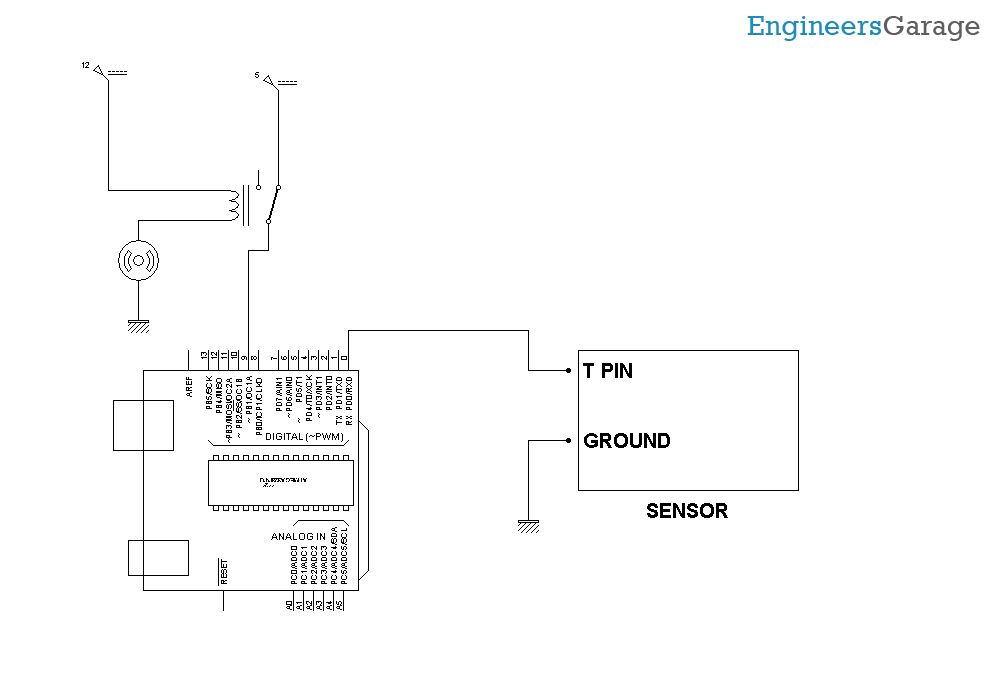 |