Microcontrollers are limited to certain tasks and typically do not have multithreading capabilities, which would allow more than one user or task at the same time without requiring multiple copies of a program or computer. Generally, microcontrollers cannot divide larger or more complex applications into multiple threads. They deal with simple sequences of code in real time, with the exception of programming loops, specific conditions, and interrupts.
Interrupts are a way to resolve urgent tasks on embedded devices. However, interrupts remain dependent on external circuits (in the case of hardware interrupts) or on integrated peripherals (in the case of timer interrupts).
Keep in mind that interrupts are intended to make microcontrollers respond to specific events in real time and not to strict deadlines. As a result, there is no guarantee of timely execution of critical tasks because interrupts in microcontrollers are inherently prioritized. Additionally, despite best coding practices, an interrupt service routine can be very long. It also suspends the main execution code, which may include other urgent tasks.
The solution? A real-time operating system (RTOS) can be used to meet strict operational deadlines. There are several RTOS available for microcontrollers, and free RTOS is popular with commercial versions available.
Technically, FreeRTOS is not a full-fledged real-time operating system, but a real-time scheduler designed for microcontrollers. With the support of FreeRTOS, you can prioritize built-in tasks so that they are executed within strict deadlines.
In this project, we will upload FreeRTOS to the Arduino UNO to learn how it schedules built-in tasks. In this case, it will be to light LEDs. This project can also be run on ESP8266, ESP32 or any other Arduino compatible microcontroller board.
Required components
1. Arduino UNO x1
2. LEDx4
3. Resistors 330Ω x4
4. Test board
5. Jumper wires/connection wires
How FreeRTOS works
Microcontrollers have a single core, which means they can only perform one task simultaneously. FreeRTOS allows task scheduling, so it appears that multiple events are running simultaneously. This is called real-time scheduling. In reality, only one task is active at a time in single-core microcontrollers, and the rest remain inactive.
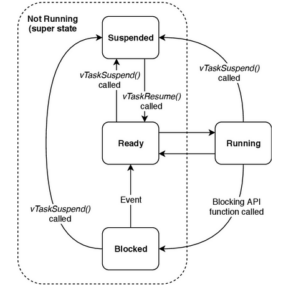
FreeRTOS divides inactive tasks into three states…
1. Ready state: Tasks in the ready state are available for scheduling through the FreeRTOS scheduler. These tasks are assigned memory and processor resources according to the scheduling algorithm. The algorithm sets the schedule for tasks in the ready state based on the priority assigned to them. These tasks are not blocked or suspended. So they are not running, but waiting to run.
2. Blocked state: Tasks in blocked state are not in the scheduler queue. Instead, they are blocked by the scheduler and remain inactive indefinitely. The blocked state depends on an external interrupt or a resource such as a mutex, semaphore, or counting semaphore. Another reason for a blocked and inactive task could be its periodic nature – meaning that it is periodically delayed in the main loop.
3. Suspended state: Inactive tasks in blocked state can only be executed when a respective interrupt is received or a required resource is used. But some inactive tasks are explicitly delayed by the developer and then placed in a queue. Often these tasks are scheduled when specific conditions are met or after another task has run. For example, a developer might suspend printing a sensor reading value on a display unit until it is read and converted by the ADC.
The FreeRTOS API provides a vTaskSuspend function that explicitly suspends a task and a vTaskResume function that resumes the task.
A task can transition through a blocked, ready, suspended, and running state multiple times during its multitasking lifetime, as shown in the flowchart below.

In Arduino, each task is defined as a block of code wrapped in its own function. FreeRTOS allows the creation of tasks that call a respective function. Each task is given a priority. FreeRTOS automatically defines the task scheduling algorithm during execution time, according to the assigned priorities and the availability of processing resources.
Installing FreeRTOS
FreeRTOS is available in the Arduino library. To incorporate FreeRTOS into an Arduino application, simply include the library in the sketch. But first, install it in the Arduino IDE.
To do this, navigate to Tools->Manage Libraries and search for FreeRTOS. Go to the FreeRTOS library written by Phillip Steven. Install the library.

Now, you can easily include FreeRTOS in an Arduino application by importing the library into the sketch using this instruction…
#includeArduino_FreeRTOS.h>
Creating and prioritizing tasks
The FreeRTOS API provides an xTaskCreate function to create tasks. The function has this prototype…
BaseType_t xTaskCreate(
TaskFunction_t pvTaskCode,
const char * const pc_name,
configSTACK_DEPTH_TYPE usStackDepth,
void *pvParameters,
UBaseType_t uxPriority,
TaskHandle_t *pxCreatedTask
);
The following arguments are needed…
- pvTaskCode: The pointer to the task's defined function. The task is implemented as an infinite loop. The pointer is passed as an argument to the function. The task can also be deleted.
- pcname: The name of the callback function that performs the task. The function must not return a value or exit.
- usStackDepth: The size of the stack in the number of words allocated to the task. In a 32-bit microcontroller, each word is four bytes. Therefore, if the stack size is set to 100, 400 bytes will be allocated to the task.
- pv parameters: The value of the parameter, which is passed as an argument to the task function.
- uxPriority: The priority set for the task, which can be a positive integer or -1. If set to -1, the priority will be set to undefined. The larger the integer (which is passed as an argument), the higher the priority of the task. For example, a task with priority 3 has a higher priority than a task with priority 2. The lowest priority is 0.
- pxCreatedTask: The role identifier for the task. The identifier can be used to delete the task.
Configuring the task execution sequence
FreeRTOS runs the highest priority task first. The remaining tasks are performed when resources are available or in periodic shifts. Typically, you need to define the initial sequence of tasks. This applies to performing initial tasks. If tasks should be executed in a predetermined order, this can be defined using the FreeRTOS API function vTaskDelayUntil. This function allows you to set a delay before the task runs for the first time.
Circuit Connections
To demonstrate FreeRTOS as a task scheduler, we will light LEDs on the Arduino. For this project, we used four LEDs and connected them with GPIO8, GPIO9, GPIO10 and GPIO11 of Arduino.

The LEDs are interfaced so that they glow when the GPIO sends a LOW signal output.
After making the circuit connections, upload the following sketch to the Arduino.
How it works
FreeRTOS is used to perform four different tasks. Each task turns on one LED light and turns off the other LEDs. A message is printed on the serial monitor indicating the execution of a certain task.
- The task that turns on the LED connected to GPIO8 has the highest priority of 3. It is scheduled to run after 100 milliseconds on the first run.
- The task that turns on the LED connected to GPIO9 has priority 2. It is scheduled to be executed after 110 milliseconds in the first execution.
- The task that turns on the LED connected to GPIO10 has priority 1. It is scheduled to be executed after 120 milliseconds in the first execution.
- The task that turns on the LED connected to GPIO11 has the lowest priority, 0. It is scheduled to run with a delay of 50 milliseconds.
Initially, tasks must be performed in this predefined order. Then, tasks are executed according to their priority and availability of processing resources.
The code
The sketch begins by importing the Arduino_FreeRTOS.h library. In the setup function, the transmission rate for communicating messages to the serial monitor is 9600 bps. The execution of the setup function is indicated by printing a message on the serial monitor.
The LEDs are connected to Arduino pins that are configured as digital outputs using the pinMode function. Tasks are created with priorities 3, 2, 1, and 0 using the FreeRTOS API xTaskCreate function. All tasks receive a stack of 100 words. Tasks are linked to the MyTask1 , MyTask2 , MyTask3 , and IdleTask callback functions.
The loop function is empty because the built-in tasks will be executed by the FreeRTOS scheduler. The first task is defined in the MyTask1 function. It turns on the LED that is connected to GPIO8, turning off all other LEDs. After execution, 'Task1' is printed on the serial monitor. The task is scheduled to run after 100 milliseconds using the vTaskDelay function when first run.
The second task is defined in the MyTask2 function. It turns on the LED that is connected to GPIO9, turning off all other LEDs. After execution, 'Task2' is printed on the serial monitor. The task is scheduled to run after 110 milliseconds using the vTaskDelay function when first run.
The third task is defined in the MyTask3 function. It turns on the LED that is connected to GPIO10, turning off all other LEDs. After execution, 'Task3' is printed on the serial monitor. The task is scheduled to run after 120 milliseconds using the vTaskDelay function when first run.
The last task is defined in the MyIdleTask function. Turns on the LED that is connected to GPIO11 (Yellow LED), turning off all other LEDs. After execution, 'Idle State' is printed on the serial monitor. The task is scheduled to run periodically after 50 milliseconds.
This task is only performed when the microcontroller is not busy performing other tasks. Since it is delayed by 50 milliseconds, it must be run periodically.
Results
The following log of FreeRTOS task execution is displayed on the serial monitor.

The LEDs are toggled by the FreeRTOS scheduler.
(Link to P35-DV demonstration video)
Conclusion
The serial monitor log indicates that tasks initially ran in the predefined pattern defined by the vTaskDelay function. Subsequently, tasks are executed according to their priority and availability of processing resources.
Since the idle task runs periodically every 50 milliseconds, the LED connected to GPIO11 appears to stay lit. The LED connected to GPIO8 stays on longer because the task responsible for turning it on has the highest priority and lasts the longest. The LED connected to GPIO9 lights up intermittently because the task responsible for turning it on does so whenever task 1 is not running. The LED connected to GPIO10 appears off because the task responsible for turning it on rarely gets a chance.