In the previous tutorial, we discussed multiplexing seven-segment displays (SSD). Continuing with display devices, in this tutorial we will cover how to interface character LCD when using Arduino. Character LCDs are the most common display devices used in embedded systems. These low-cost LCDs are widely used in industrial and consumer applications.
Display devices in embedded systems
Most devices require some type of display for a variety of reasons. For example, an air conditioner requires a display that indicates temperature and AC settings. A microwave oven requires a display to present the timer, temperature, and selected cooking options. A car's dashboard uses a display to monitor distance, fuel indication, mileage and fuel efficiency. Even a digital watch requires a display to show the time, date, alarm, and modes.
There are also several reasons why industrial machines and electrical or electronic devices require a display.
Display devices used in embedded circuits—whether they are industrial devices, consumer electronics, or sophisticated devices—are used to indicate some information or to facilitate human-machine interface.
For example, LEDs are used as indicators of mutually exclusive conditions. SSDs are used to display numerical information. Liquid crystal displays (LCDs), TFTs, and OLED displays are used to present more complicated information in embedded applications. Often this complication arises due to the text or graphical nature of the information or interface.
LCDs are the most common display devices used in all types of embedded applications. There are two types of LCD monitors available:
1. Character LCDs
2. Graphic LCDs.
Character LCDs are used where the information or interface is textual in nature. Graphic LCDs are used where the information or interface is graphic in nature. Graphic LCDs used to design human-machine interfaces can also have touch screens.
Character LCDs
Character LCDs are useful for showing textual information or for providing a text-based human-machine interface. It is even possible to display some minimal graphics on these LCDs. They are low-cost LCD monitors that suit a wide range of embedded applications.
Character LCDs generally do not have touch screens. And unlike graphic LCDs, these LCDs do not have continuous pixels. Instead, the pixels in character LCDs are organized as a group of pixels or dot matrix of pixels of fixed dimensions.
Each one-pixel dot matrix is intended to display a text character. This group of pixels usually has dimensions 5×7, 5×8 or 5×10 – where the first digit indicates the number of columns of pixels and the second digit indicates the number of rows of pixels. For example, if each character has dimensions 5x8, then the character will be displayed by lighting 5 columns and 8 rows of pixels/dots. This may include pixels used to show the cursor.
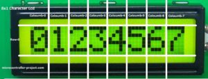
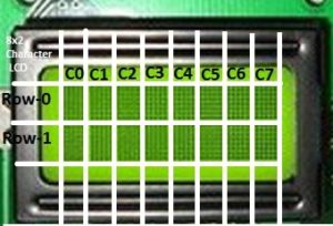
Character LCDs are classified by their size, which is expressed as the number of characters that can be displayed. The number of possible characters that can be displayed on the LCD at a time is indicated as the number of character columns and the number of character lines.
The common size of character LCDs is 8×1, 8×2, 10×2, 16×1, 16×2, 16×4, 20×2, 20×4, 24×2, 30×2, 32× 2, 40×2, etc. For example, a 16x2 character LCD can display 32 characters at a time in 16 columns and 2 rows. Typically, characters are displayed as an array of black dots, while the LCD backlight can be a monochromatic color such as blue, white, amber, or yellow-green.

LCDs are available in one of three types:
1. Twisted Nematic (TN)
2. Super Twisted Nematic (STN)
3. Focus Super Twisted Nematic (FSTN).
Character LCDs can use any of these types. TN types are low cost, but have a narrow viewing angle and low contrast. FSTN offers the best contrast and widest viewing angle, but they are more expensive. Even character LCDs using FSTN display are still cheaper compared to graphic LCDs, TFTs and OLEDs.
Most character LCDs use LED backlighting, and the backlight color can be white, blue, amber, or chartreuse. The other backlight types in character LCDs include EL, CCFL, internal power, external power, and 3.3 and 5V backlight. EL and LED backlights are the most common. The LCD can have a reflective, trans-reflective or transmissive back polarizer.
Display quality depends on the type of LCD, backlight, and the nature of the back polarizer used in the LCD panel. When selecting an LCD panel for an embedded application, it is important to decide on the quality of the LCD display according to the requirements. This includes the application, device class, nature of use (such as indoor or outdoor), target users of the device, intended user experience, operating conditions (such as temperature and operating voltage), and cost limitations.
For example, a character LCD that is to be used for human-machine interface should have better contrast, a wide viewing angle, and good backlight.
The following table summarizes the important features of any character LCD.
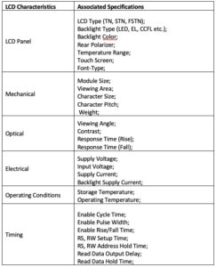
Even on a character LCD, a large number of pixels need to be controlled to display text. A 16x2 character LCD where each character is 5x8 pixels means that a total of 1280 pixels (16x2 characters x 5x8 pixels) must be controlled. This requires interfacing the pixels into 16 rows (2 rows of characters x 8 rows in each character) and 80 columns (16 columns of characters x 5 columns in each character) of connections.
This occurs when the pixels are black dots and only require turning the controller on or off to display text characters. In a typical microcontroller, there are not that many I/O pins that can be dedicated to controlling the pixels of an LCD panel. This is why LCD modules have built-in controllers that control the LCD pixels. The integrated controller can interface with a microcontroller or processor through an 8/4-bit parallel port or a serial interface (such as I2C). The integrated controller receives data and commands from the microcontroller/processor to display text on the LCD panel through a 4/8-bit parallel or serial interface.
In fact, the LCD module is a complete embedded system composed of an LCD panel, LCD driver, LCD controller, LED backlight, internal flags, address counter, display data RAM (DDRAM), character generator ROM (CGROM ), character generating RAM (CGRAM), Data Register (DR), Instruction Register (IR) and Cursor Control Circuit.
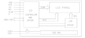
LCD module functional blocks
A character LCD module has these functional blocks:
1. LCD panel. Character LCDs have a dot-matrix LCD panel. Text characters are displayed on the panel according to the commands and data received by the integrated controller.
2. System interface. This module has a 4 and 8 bit interface for connecting to microcontrollers/processors. Some LCD modules also have an integrated serial interface (I2C) for communicating with a controller. Interface selection (4 bits or 8 bits) is determined by the DL bit of the Instruction Register (IR).
3. Data Record (DR). Data Register is an internal register that stores data received by the microcontroller through the system interface. The value filled in the data register is compared with character patterns in the Character Generator ROM (CGROM) to generate different pattern characters.
4. Instruction Record (RI). The Instruction Register is an internal register that stores instructions received by the microcontroller through the system interface.
5. Character generator ROM (CGROM). It is an internal read-only memory (ROM) in the LCD module where the standard character patterns are stored. For example, a 16×2 LCD, CGROM module has 5×8 dots, 204 character patterns and 5×10 dots of 32 character patterns that are stored. Thus, the 204 character patterns are permanently stored in the CGROM.
6. Character generating RAM (CGRAM). User-defined characters can also be displayed on a character LCD. Custom character patterns are stored in CGRAM. On the 16×2 LCD, 5 characters of the 5×8 pixels can be defined by a user program. The user needs to write the font data (which is the character pattern that defines which pixels/dots must be on and which must be off to correctly display the character) to generate these characters.
7. View data RAM (DDRAM). The data sent to the LCD module by the microcontroller remains stored in DDRAM. In 16×2 character LCD, DDRAM can store a maximum of 80 8-bit characters, where maximum 40 characters for each line can be stored.

8. Address counter (AC). The address counter is an internal register that stores DDRAM/CGRAM addresses that are transferred by the instruction register. The AC reads the DDRAM/CGRAM addresses from bits DB0-DB6 of the instruction register. After writing to DDRAM/CGRAM, the CA is automatically increased by one, while after reading from DDRAM/CGRAM, the CA is automatically decreased by one.
9. Busy Flag (BF). Bit DB7 of the instruction register is a busy flag of the LCD module. When the LCD is performing some internal operations, this flag is set (HIGH). During this time, the instruction register does not accept any new instructions from the microcontroller through the system interface. New instructions can be written to the IR, but only when the busy flag is clear (LOW).
10. Cursor/blinker control circuit. This controls the ON/OFF status of the cursor/blink at the cursor position. The cursor appears at the DDRAM address currently defined in the AC. For example, if AC is set to 07H, the cursor will be displayed at DDRAM address 07H.
11. LCD Controller. It controls the LCD panel and display. In 16×2 character LCD, the LCD driver circuit consists of 16 common signal drivers and 40 segment signal drivers.
12. Timing generation circuit. It generates the timing signals for the operation of internal circuits such as DDRAM, CGRAM and CGROM. The timing signals for reading the RAM module (DDRAM/CGRAM) are generated separately to display characters and timing signals for the internal operations of the LCD's integrated controller/processor. This is so that the display does not interfere with the internal operations of the LCD module's integrated controller.
Character LCD Interface
Most character LCDs have a 14- or 16-pin system interface for communicating with a microcontroller/processor. The 16-pin system interface is the most common.
It has this pin configuration:
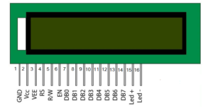
LCD module system interface pin descriptions are summarized in this table:
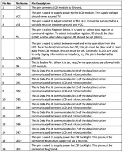
To interface the LCD module with a microcontroller or Arduino, the microcontroller's digital I/O pins must be connected to the RS, RW, EN, and data pins DB0 to DB7.
Typically, Arduino (or any microcontroller) does not need to read data from the LCD module, so the RW pin can be connected to ground.
- If the LCD is interfaced with the Arduino in 8-bit mode, the RS, EN and all data pins must be connected to the Arduino's digital I/O pins.
- If the LCD is interfaced to the Arduino in 4-bit mode, the RS, EN and data bits DB7 to DB4 must be connected to the Arduino's GPIO.
In 4-bit mode, two pulses are required on the EN pin to write data/instructions to the LCD. At first, the largest data nibble or instruction is latched. Then, in the second pulse, the lower data/instruction nibble is transferred.
In 8-bit mode, all 8-bit data/instructions are written to the LCD in a single pulse on the EN pin. Therefore, 4-bit mode saves microcontroller pins, but has a slight latency compared to 8-bit mode of operation. 8-bit mode suffers from less latency but involves 4 extra microcontroller pins.
It is also possible to interface the LCD module with Arduino using a serial to parallel converter. So only two Arduino pins are needed to interface with the LCD module.
The ground pin of the LCD module (pin 1) must be connected to ground while the VCC pin (pin 2) must be connected to the supply voltage. The 3.3 or 5V pin of Arduino can be used to supply voltage to the LCD module. The VEE pin must be connected to the variable terminal of a variable resistor, and the fixed terminals of the variable resistor must be connected to VCC and ground.
The LED+ (pin 15) must be connected to VCC through a current limiting resistor and the LED (pin 16) must be connected to ground.
How Character LCD Works
It is possible to read/write data with the LCD module. To write data/instructions to the LCD module, the RW pin must be clear. So, if RS is configured, the 8-bit data sent by the microcontroller is stored in the data register (DR) of the LCD module. This 8-bit data sent by the microcontroller will be stored in the instruction register (IR) of the LCD module.
Data is transferred from the microcontroller to the LCD when a HIGH to LOW pulse is applied to the EN pin of the module.
When data is sent to the LCD module (RW=0, RS=1, EN=1->0), it is written to DDRAM and the LCD Address Counter is increased by one. The LCD controller compares the 8-bit data to the CGROM addresses and displays the appropriate character on the LCD at the associated DDRAM address. This serves as an instruction to show that the view has been received.
When the instruction is sent to the LCD module (RW=0, RS=0, EN=1->0), it is stored in the instruction register and according to the predefined instruction set of the LCD controller, the appropriate operation is executed on the display (to enable display, disable display, enable cursor, disable cursor, clear DDRAM, etc.).
Sometimes the microcontroller may need to read data from the LCD. A microcontroller can read the contents of the LCD's instruction register, DDRAM and CGRAM. To read data from the LCD, the RW pin must be configured. When the RW is set and the RS is clear, the microcontroller reads the contents of the Instruction Register (IR) – including the busy flag (DB7 of the IR) and the address counter (DB6 to DB0 of the IR) – when applying a pulse from HIGH to LOW on the EN pin.
When RW is set and RS is set, the microcontroller reads the contents of DDRAM or CGRAM according to the current value of the address counter by applying a HIGH to LOW pulse on the EN pin.
Thus, the microcontroller reads the contents of the instruction register when: RW=1, RS=0 and EN=1->0 .
It reads the contents of DDRAM/CGRAM in the current address counter when: RW=1, RS=1 and EN=1->0 .
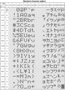
LCD character set
The following characters, with the given data register patterns and values, are supported on a 16x2 LCD.
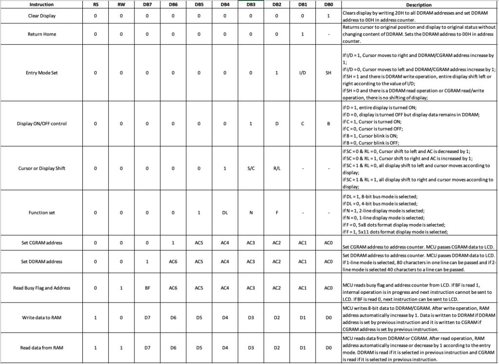
LCD commands
A 16x2 LCD module supports the following 8-bit commands:
LCD functions using Arduino
If the LCD module is interfaced with typical microcontrollers (8051, PIC, AVR, etc.), the RS, RW, EN and data bits need to be configured individually to perform read/write operations.
Arduino has a liquid crystal library (LiquidCrystal.h) available that makes programming the LCD with Arduino extremely easy. This library can be imported by the following statement:
#include
The library uses these methods to control a character LCD:
1. Liquid crystal
2. lcd.begin
3. LCD.clear
4. lcd.home
5. lcd.setCursor(column, row)
6. lcd.write (data)
7. lcd.print(data)/lcd.print(data, BASE)
8. lcd.cursor
9. lcd.noCursor
10. lcd.blink
11. lcd.noBlink
12. LCD screen
13. lcd.noDisplay
14. lcd.scrollDisplayLeft
15. lcd.scrollDisplayRight
16. lcd.autoscroll
17. lcd.noAutoscroll
18. lcd.leftToRight
19. lcd.rightToLeft
20. lcd.createChar(num,data)
LiquidCrystal Method
This method is used to create a Liquid Crystal object. The object must be created according to the LCD module circuit connections when using Arduino.
The object uses the Arduino pin numbers as arguments. The pin numbers where RS, RW, EN and the data pins (DB7-DB0 for 8-bit mode and DB7-DB4 for 4-bit mode) of the LCD are connected must be passed as arguments in the object definition.
This method has this syntax:
If the LCD is connected in 4-bit mode and the R/W pin is grounded:
LiquidCrystal(rs, enable, d4, d5, d6, d7);
or
LiquidCrystal lcd(rs, enable, d4, d5, d6, d7);
If the LCD is connected in 4-bit mode and the R/W pin is also connected to the Arduino:
LiquidCrystal(rs, rw, enable, d4, d5, d6, d7);
or
LiquidCrystal lcd(rs, rw, enable, d4, d5, d6, d7);
If the LCD is connected in 8-bit mode and the R/W pin is grounded:
LiquidCrystal(rs, enable, d0, d1, d2, d3, d4, d5, d6, d7);
or
LiquidCrystal lcd(rs, enable, d0, d1, d2, d3, d4, d5, d6, d7);
If the LCD is connected in 8-bit mode and the R/W pin is connected to the Arduino:
LiquidCrystal(rs, rw, enable, d0, d1, d2, d3, d4, d5, d6, d7);
or
LiquidCrystal lcd(rs, rw, enable, d0, d1, d2, d3, d4, d5, d6, d7);
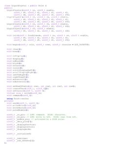
The LiquidCrystal class has this source code:
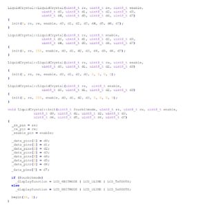
The LiquidCrystal method has this definition in the source code:
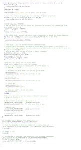
lcd.begin method
This method is used to initialize the LCD module. The function takes the size of the LCD (expressed by the number of columns and rows on the LCD) as an argument.
It has this syntax:
lcd.begin(columns, rows)
This function has the following source code:
lcd.clear method
This method clears the LCD display and positions the cursor in the upper left corner.
It has this syntax:
lcd.claro
This function has the following source code:

lcd.setCursor Method
This method positions the cursor at a certain location on the LCD panel. It takes column and row as arguments where the cursor should be placed and a subsequent character should be displayed.
It has this syntax:
lcd.setCursor(column, row)
This method has the following source code:

lcd.print method
This method is used to print text on the LCD. A string argument is required, which must be displayed at the current cursor position on the LCD. Can be based on the value passed as an optional argument – just to print numbers.
It has this syntax:
lcd.print(data)
lcd.print(data,BASE)
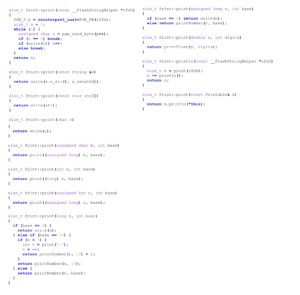
This method comes from the Print.h library included in the LiquidCrystal.h library.
This method has the following source code:
How to check the LCD
A common concern when interfacing the LCD module is identifying whether the LCD module is actually working or not. When connecting the LCD to the Arduino (or any other MCU), if only the bottom line of the LCD lights up, the LCD module is working.
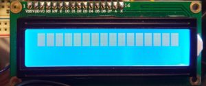
When connecting the LCD to the Arduino, if both lines of the LCD (16×2 LCD) glow, then the LCD is not working properly.
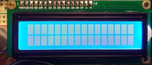
Sometimes when you try to print to the LCD, nothing happens except the bottom line of the LCD lighting up. In this case, the possible reasons may be one of the following:
1. There may be loose connections between the Arduino (MCU) and the LCD module.
2. The LCD module may have been connected in reverse pin order (i.e., instead of pins 1 to 16, the circuit connections may have been made from pins 16 to 1 of the LCD module).
3. There may be a short circuit between the LCD terminals due to faulty soldering.
4. The LCD contrast on the VEE pin may not have been adjusted correctly. If contrast adjustment does not work, try connecting the VEE pin directly to ground so that the LCD module is adjusted to maximum contrast.
5. If after checking all circuit connections the LCD panel still does not display text, check whether the code loaded into the Arduino is correct or not. For example, it is possible that if the LCD display is not cleared after initialization, useless values may be displayed on the LCD instead of the intended text.
Recipe: Print text on 16X2 character LCD
In this tutorial, we will print simple text on the 16×2 LCD panel of Arduino UNO .
Required components
1. Arduino UNO x1
2. 16×2 character x1 LCD
3. 10K Pot x1
4. 330 Ohm resistor or any low value resistor x1
5. Test board x1
6. Male-to-male bonding wires or connecting wires
Circuit Connections
The LCD module used in this project is the JHD162A. This is a 16×2 LCD module with 5×8 character dots. The LCD module has a 16-pin interface. The LCD interfaces with the Arduino in 4-bit mode.
Pin 1 (GND) and 16 (LED) of the LCD module are connected to ground while pin 2 (VCC) is connected to VCC. Pin 15 (LED+) of the LCD module is, once again, connected to VCC through a small value resistor. Pin 3 (VEE) is connected to the variable terminal of a potentiometer while the fixed terminals of the potentiometer are connected to ground and VCC.
The R/W pin is connected to ground as the Arduino will only write data to the LCD module. RS, EN, DB4, DB5, DB6 and DB7 pins of LCD are connected to pins 13, 11, 7, 6, 5 and 4 of Arduino UNO respectively. The breadboard provides the common ground. 5V powers the rail from one of the ground pins and the 5V pin of the Arduino UNO, respectively.
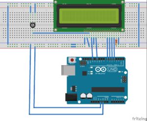
Circuit Diagram
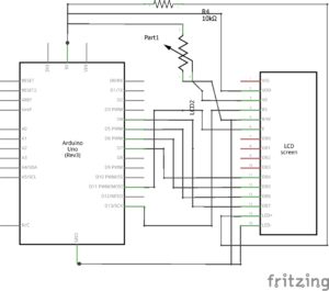
Arduino Sketch
How the project works
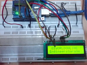
The LCD module is connected to the Arduino in 4-bit mode. First, the LCD is initialized and the screen is cleaned to eliminate any useless values in the DDRAM. The cursor is placed in column 1 of line 0 and the text “EEWORLDONLINE” is printed on the LCD.
Then the cursor is moved to column 0 of row 1 and the text “EngineersGarage” is printed on the LCD. A delay of 750 milliseconds is given and the LCD is cleared again.
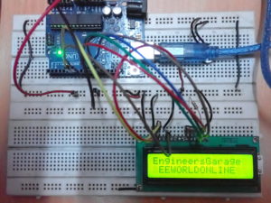
The cursor is moved to column 0 of row 0 and the text “EngineersGarage” is printed on the LCD. The cursor is then moved to column 1 of line 1 and the text “EEWORLDONLINE” is printed on the LCD.
The Arduino UNO will keep repeating the code and alternatively printing both text strings on lines 0 and 1.
Programming guide
The LiquidCrystal.h library is imported into the code. Then, an object defined by the variable “lcd” is defined for the LiquidCrystal class.
#include
//LCD Liquid Crystal(RS, E, D4, D5, D6, D7);
Liquid Crystal LCD (13, 11, 7, 6, 5, 4);
In the configuration function, the LCD is initialized at 16×2 size, using the Begin method like this:
null configuration
{
lcd.begin(16, 2);
}
In the loop function, the LCD display is cleared using the clear method and the cursor is placed in column 1 of row 0 using the setCursor method. The text “EEWORLDONLINE” is printed using the print method on the “lcd” object. Similarly, the text “EngineersGarage” is printed in column 0 of line 1. A delay of 750 milliseconds is given using the delay function.
empty loop
{
lcd.claro;
lcd.setCursor(1, 0);
lcd.print(“EEWORLDONLINE”);
lcd.setCursor(0, 1);
lcd.print(“EngenheirosGaragem”);
delay(750);
Then the LCD display is cleared again and the position of both texts is reversed.
lcd.claro;
lcd.setCursor(0, 0);
lcd.print(“EngenheirosGaragem”);
lcd.setCursor(1, 1);
lcd.print(“EEWORLDONLINE”);
delay(750);
}
The body of the loop function will continue to repeat until the Arduino is turned off. Therefore, both texts continue to be displayed on the LCD module, alternating their position between lines 0 and 1 of the panel.
In the next tutorial, we will discuss how to use text scrolling in the LCD module.

