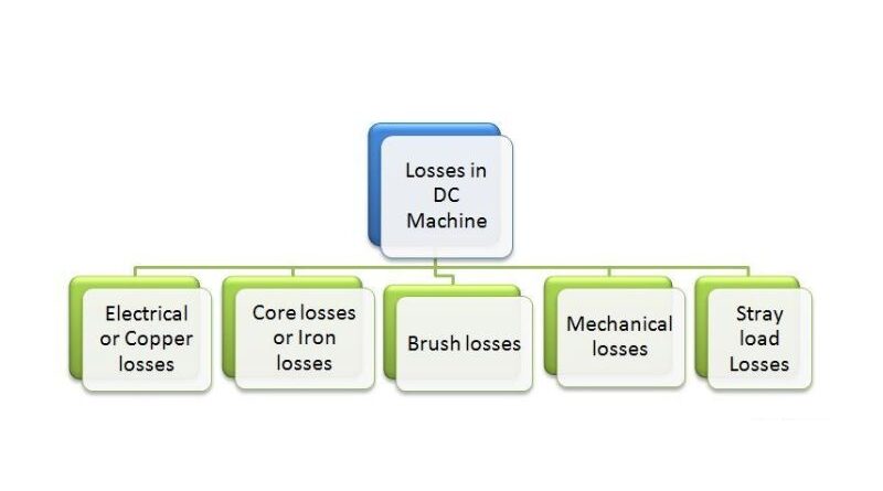
Types of losses
The losses of a direct current machine (generator or motor) can be divided into three classes. They are
1. Copper losses
This loss generally arises from the current in the various windings of the machine. The different winding losses are:
2. Iron losses
This loss occurs in the armature of a DC machine and is due to the rotation of the armature in the magnetic field of the poles. There are two types, namely
Hysteresis loss

Hysteresis losses occur in the armature winding of the DC machine because any part of the armature is exposed to the reverse magnetic field as it passes under the following poles. The above figure shows the 2-pole DC machine with rotating armature. Note a small, low section of the armature winding. As soon as piece ab is under pole N, the magnetic lines go from a to b. Half a turn away, there is an identical piece of iron under the S pole, and the magnetic lines go back and forth to reverse the magnetism in the iron. To constantly reverse the molecular magnets in the armature core, a certain amount of energy must be expended, called hysteresis loss. The Steinmetz formula indicates this.
The Steinmetz formula is:
Hysteresis loss P H =ηB 16 Max fV watts
Eddy's current loss

When using a continuous cast iron core, the resistance to the eddy current path is low due to the large cross-section of the body. Consequently, the eddy current strength and eddy current losses are enormous. The eddy current intensity can be reduced by keeping the core resistance as high as possible. Core strengths can be greatly increased by making the core from thin, round iron sheets called laminations (see illustration). The laminations are isolated from each other by a layer of varnish. The insulating layer has high resistance; therefore, little current flows from one lamination to another. Furthermore, because each lamination is extremely thin, the resistance to current flowing across the width of the lamination is quite large. Therefore, laminating a core increases the resistance of the core, which reduces eddy current and therefore eddy current losses.
Eddy current loss P t =K t b 2 Max F 2 T 2 V watts
Where k t = constant
constant ( K t ) depends on the core resistance and the measurement system used.
Mechanical loss
These losses are due to friction and air resistance.
- Friction losses arise from friction in bearings, brushes, etc.
- Air friction from the rotating coil causes air loss.
Constant and variable losses
Constant losses
Losses in a DC generator that remain constant under all loads are called continuous losses. The operating losses in a DC generator are:
Variable losses
Those losses in a DC generator that vary with load are called variable losses. Variable losses in a DC generator are:
Copper loss in the armature winding (I 2 R A )
Copper loss in series field winding (I 2 se R se )
Total Losses = Constant Losses + Variable Losses.
This copper loss is generally constant in shunt and compound generators.