This is a simple tutorial on arduino, ldr (light dependent resistor)/photoresistor sensor and piezoelectric buzzer. The output sound level of the piezo buzzer varies depending on the Arduino depending on the intensity of the light emitted at the LDR/light sensor. An LED will also disappear by the Arduino depending on the intensity of the light thrown at the photoresistor. The DIY project is the same as the basic electronics project we created in our electronics class “ Light Sensor ” using passive components (Resistors, Transistors, LDR, Led, Buzzer). The difference is that in our DIY project we will use a dedicated microcontroller (Arduino uno) to control the sound level of the buzzer and the LED fading depending on the value of the LDR light sensor.
Arduino buzzer led and LDR
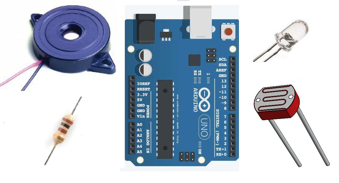
Piezoelectric buzzer
The Piezo doorbell is a small electronic component. It emits a tone when voltage is supplied across its power pins. Typically the piezo buzzer operates on 5 volts, but 12 volt versions are also available. The tone/sound produced by the piezoelectric buzzer depends on the power supplied to it. If the power is low, the output tone will be low and if the power is high, the tone/sound will be high. A 5-volt piezoelectric buzzer can emit a 3-volt tone. The output tone increases if we increase the voltage by 3 and the maximum tone we will get will be 5 volts. The piezo buzzer has two pins. Vcc to which we supply +ve voltage and Gnd which we connect to the power supply ground.
LDR (Light Dependent Resistor)/Photoresistor
LDR is a special resistor. The resistance of the LDR varies when light is shined on it. Its resistance increases and decreases depending on the intensity of the light shined on it. It normally has high resistance and when exposed to light its resistance decreases. This unique characteristic of the LDR makes it possible to use it in automatic public lighting activation/deactivation circuits. It is used as a standalone light switch. Light intensity and brightness can be controlled using LDR.
In our project we will also measure the light intensity with LDR (light dependent resistor). Now, how do we measure it? See the diagram below.
|
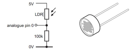
LDR Arduino measuring light intensity
|
A voltage divider circuit is shown above. Remember that LDR is a resistor. when there is no light on the LDR, very little current will flow through the circuit. The 100k resistor will be at 0 potential. There will be no voltage across the 100k resistor. Now when a light source is brought closer to the LDR. Its resistance will begin to decrease and current will begin to flow through the circuit. Voltage begins to appear at the 100 k resistor. The greater the intensity of the light thrown into the LDR, the more voltage appears across the 100 k resistor. When the amount of light thrown onto the LDR sensor increases the threshold value, the LDR resistance becomes almost 0.
The voltage that appears across the 100k resistor is read by the Arduino's analog pins and translated for later use (controlling the Arduino buzzer and LED fade mechanism).
Project circuit diagram
Arduino two digital pins and one analog pin are used in the project. Two Arduino digital pins are carefully selected. I choose Arduino digital pins (~11 and ~6) which can output a pwm signal. I hope you know the PWM (Pulse Width Modulation) technique. Otherwise, just for this tutorial, use it (pwm) as a way to generate a variable signal on digital pins. By variable signal I mean output voltage between 0-5 volts. It can be 0.5, 1, 1.2, 3.5, 4.1 volts, any voltage between 0-5 volts.
One leg of the Arduino buzzer is connected to pin 11 of the Arduino and the other is pulled up. The positive leg of the LED is connected to pin #6 of the Arduino and the other end is pulled up. 5 volts supplied to the buzzer and LED can be from the 5v pin of the Arduino. The 220 ohm resistor in series with the buzzer and LED is used for current limiting purposes.
The midpoint of the LDR and 10 k resistor voltage divider circuit is connected to the analog channel 0 of the arduino uno. The 5 volt Ldr input can also be provided with the Arduino 5 volt output rail. The circuit diagram of the project is given below.
Arduino Audible Alarm with Light Dependent Resistor (LDR)/Photoresistor
Coming to the code part of the project. The code is written in Arduino IDE and is free for everyone. You can use and modify it according to your needs. In the code I first defined the variables for arduino analog channel 0 as sensor buzzer arduino pin (arduino pin #11) as Buz and led arduino pin (arduinp pin #6) as Lead . In the setup function I declared the Buz and Led pins as output. Since they are outputting voltage or Pwm (Pulse Width Modulated) signal for buzzer and LED dimming.
In the configuration function, the Arduino serial port is also initialized with a baud rate of 9600. The Arduino serial port is initialized to see the voltage measurement by analog channel 0 to which the LDR output is connected. Serial.begin(9600) instruction is initializing the Arduino serial port.
In the loop function, first I am reading the LDR light intensity value. The int senValue=analogRead(sensor) statement is reading the output voltage of the LDR across the 10k resistor. The read value is stored in variable senValue .
- Arduino is a 5 volt tolerant device. Its gpio pins can generate 5 volt TTL signal. Likewise, its gpio pins can be exposed to the 5v TTL signal as input. Greater than 5V may destroy the GPIO pin. Therefore, the input voltage on the Arduino pins should remain between 0-5 volts. I supplied 5 volts to the LDR keeping the above restriction in mind.
- The Arduino's analog channel can also read a maximum of 5 volts. Arduino ADC (analog to digital channel) has 10-bit width or 10-bit resolution. It means it can generate values up to 1024. 1024 represents 5 volts. 512 represents 2.5 volts and vice versa.
- So if the voltage across the 10k resistor is 2 volts, the arduino's analog channel 0 will read it and give us an integer value of 410. ((410/1024)*5v = 2v).
The same strategy above is applied in the code. When the voltage across the 10 k resistor increases by 1.5 volts (ADC value 310), the buzzer and LED are activated and activated with the same voltage that appears across the 10 k resistor . The if statement in the code is checking 1.5 volts or integer value 310 by the ADC. The buzzer and LED will only operate at voltages greater than 1.5 volts.
- Unlike Arduino ADC, Arduino PWM provides 8-bit resolution. So in analogWrite(*, senValue/4) function in the code I am dividing the senValue by 4 to bring the senValue in 8-bit resolution 0-255. I hope it makes sense to you.
More advanced projects involving Buzzer and microcontroller. Click on the buttons below to visit the projects. The source code and circuit diagram of each project are free.
Home security system with Arduino
WiFi security alarm with nodemcu
Download the project code. The folder contains the arduino ide .ino project file. Please provide us with your feedback on the project. Write your comments below in the comments section.
Code/Files