In this tutorial I will teach you how to interface relays with stm32f103 microcontrollers. Stm32 microcontrollers work on 3.3 volt TTL logic. Where electrical relays take a minimum of +5 volts to make a regular connection. We need an external circuit to drive relays with stm32 microcontrollers. This post is to teach what should be used with the stm32 microcontroller to activate various relays with it. There are several methods on how to control high loads with microcontrollers. I have listed these methods in another tutorial. If you are interested in knowing how we can drive high loads with microcontrollers, just click the button below to follow the tutorial.
Methods for driving high loads with microcontrollers
Transistors are best suited with microcontrollers to drive relays. But if we have multiple relays in our design, using transistor for each relay is not the best choice. Individual transistors not only make our circuit bigger but also confusing. Fortunately, we have several ICs available on the market that contain combinations of transistors. These ICs are small in size and consume less space when compared to a single independent transistor. ULN2003 and ULN2803 are popular transistor combination ICs available in the market. The ULN2003 has 7 transistor channels and the ULN2803 has 8 transistor channels. Each channel is composed of a Darlington pair of 2 transistors. In the Darlington configuration, the current amplified by the first transistor is further amplified by the second transistor. We can conclude that each channel of the ULN2003 and ULN2803 are high current gain amplifiers. In this project I will use ULN2003 darlington pair ic. The ULN2003 in this project will work as a relay driver.
ULN2003 as relay driver
|
The individual configuration of the darlington pair in the ULN2003 ic is given on the right side. 3.3 volts from the stm32 microcontroller output pins go to the base of the first transistor. The first emitter of the transistor is inserted into the second base of the transistor. Therefore, when the first transistor turns on instantly, the second one also turns on. Current will begin to flow from 'Out' to ground. The diode on the 'COM' pin works as a fly back diode. It prevents the circuit from receiving any reverse emf generated by the relay coils. The ULN2003 can support loads requiring 50 volts and 500 mA of current.
|
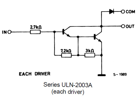
ULN2003 Single Darlington Transistor Pair Circuit
|
Design Circuit
I will turn four relays on and off with stm32 microcontroller. Four buttons are used as input to the stm32 microcontroller. These four buttons correspond to four output relays. Pressing each button will change the state of the corresponding relay. For example, if the relay is on, pressing the corresponding button will change its state to off. We can say that the buttons alternate the state of the relays with each press.
The microcontroller used in the project is stm32f103c8t6. It is built on the Cortex M3 core. Pins 0,1,2,3 of port A of stm32 microcontroller are used as output pins. Pin No. 0 of port a is connected to input 1 of the ULN2003 relay driver. Port A pin #1 is connected to input #3, pin #2 is connected to input #5, and pin #3 is connected to pin #7 of the ULN2003 relay driver.
The input buttons are connected to pins 6, 7, 8, 9 of port B. The Stm32 microcontroller has built-in pull up and pull down resistors on each individual gpio pin. We can enable and disable them in code. For our button inputs, I enabled the pull up resistors associated with each gpio (Port-B Pin#6,7,8,9). One side of the input buttons is connected to the microcontroller pins and the other side is commonly grounded.
The relays I am using in the project activate at +9 volts. I connected the relay coil at one end with a ULN2003 output and at the other +12 volts. The COM pin of the relay is grounded to the load power. The Nc pin of the relay is connected to the load and the other end of the load is connected to the positive power wire of the load. No relay pin is left untouched. The ground pin of ULN2003 is grounded with 12 volt relay power supply and with stm32 ground. Note ULN2003 GND must be commonly grounded with stm32 power supply and ULN2003 relay power supply.
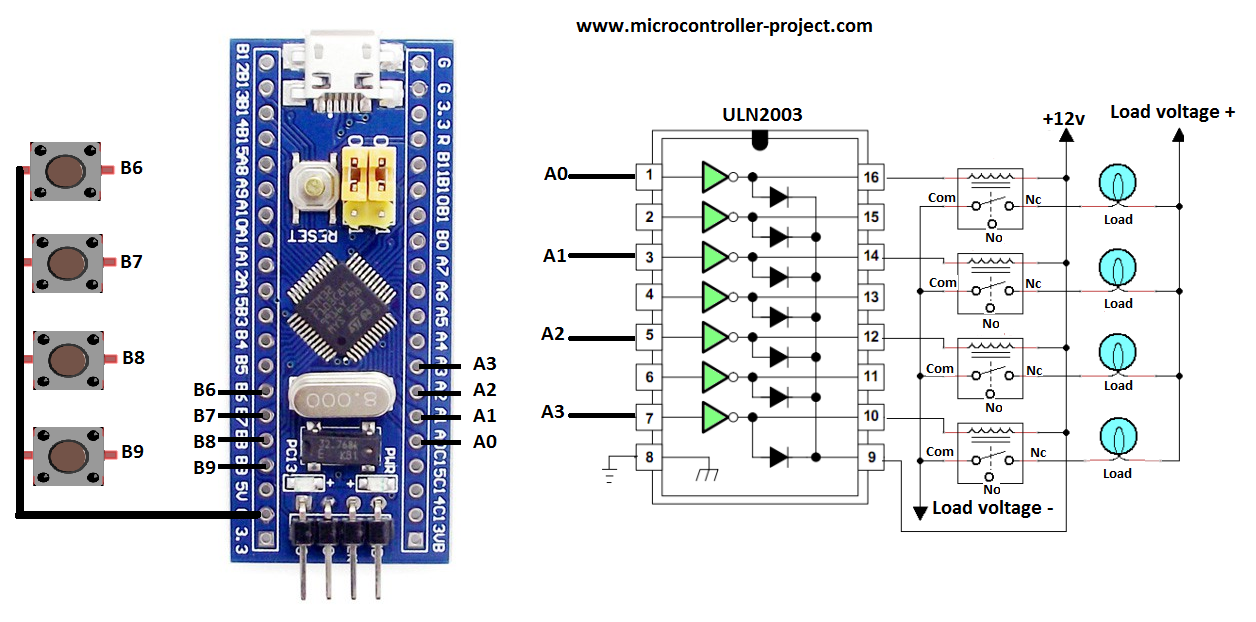
Relays with STM32 microcontroller and ULN2003 relay driver
Project code
Stm32cubemx is used for microcontroller configuration. The input and output pins are declared on it. The pull up and pull down resistors on the input pins are also activated in stm32cubemx. After configuration and settings, the project code is created and imported into Keil Uvision Arm 5 MDK IDE. Below fig are the final settings of stm32 in stm32cubemx.
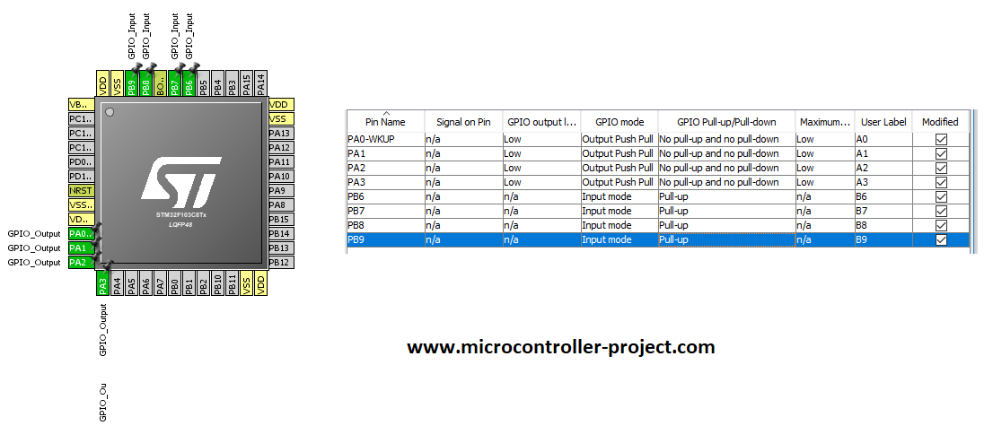
Stm32cubemx GPIOS settings for pins as input and output
If you have not worked with stm32cubemx code configurator and keil uvision mdk arm 5 and you are newbie in this field. So I have a comprehensive tutorial on getting started with stm32 cubemx and keil ide for you. Click the button below for tutorial.
Getting started with stm32cubemx and keil arm mdk
The code is written and compiled in Keil Uvision IDE. Stm32 HAL libraries are used in the project. The main logic and core of the code is in the while loop 1. The statement
if(HAL_GPIO_ReadPin(GPIOB,B6_Pin)==GPIO_PIN_RESET) //Checks if the input button has been pressed
is checking whether the button is pressed or not. The instruction uses HAL stm32 libraries to check the state of the input button. Port B pin #6 is checked in the above code. GPIO_PIN_RESET means if the pin is at low voltage (0 volts). When the button is pressed, the floor appears on this peg. The other end of the button is connected to stm32 grounding. If the above statement is true, the next statement will be executed.
HAL_GPIO_TogglePin(GPIOA,A0_Pin);
The above statement is executed right after the if statement IF the statement is true. It toggles the relay state. This statement also uses stm32 HAL libraries. The instruction toggles the state of port A pin #6.
Making the above circuit on a breadboard is difficult for a DIY project. If you are doing a DIY project on driving the stm32 relay. I suggest you use a pre-assembled relay board in your project. There are numerous relay boards available on the market containing different numbers of relays. 2, 4 and 8 channel relay boards are most commonly available in the market. These boards have ULN2003 or ULN2803 relay driver ICs installed on them. They also have status LEDs. LEDs show the status of the relays. The terminal blocks for each relay are also very useful for making connections to loads.
The above code can be used with the relay board. The connections are the same. Only you need to make the relay power and stm32 power grounds common.
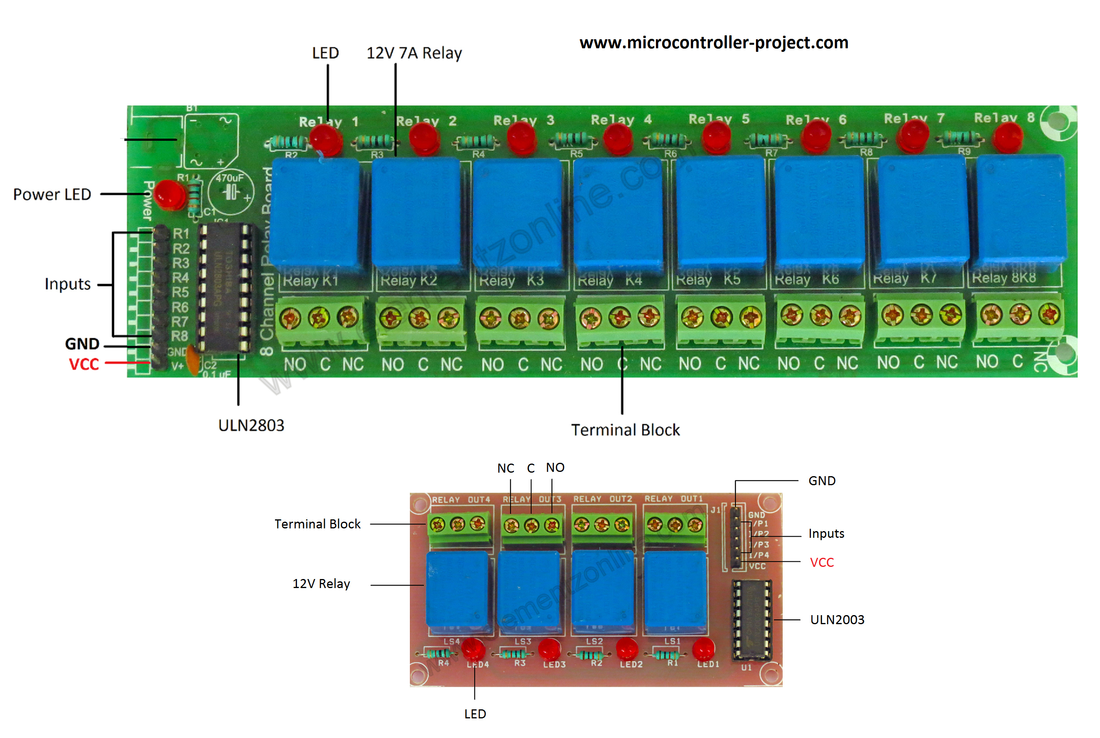
4 or 8 channel relay board for microcontroller with ULN2003 and ULN2803 relay driver
Relay boards also come with optocouplers and single transistor circuits. The code in this project can be used with any relay board containing ULN2003, ULN2803, optocouplers or individual transistors as relay drivers.
Code/Files


