Introduction
The clamping device for welding nuts and bolts requires quality assurance during the installation process. Furthermore, to assess the quality of the weld and the reliability of the process, the strength of the installation requires monitoring throughout the procedure.
To prove the reliability of the installation process, other quality assurance measures can also be integrated into the production process, potentially eliminating the need for subsequent inspections of weld nuts and bolts.
1. Overview
This standard document covers tightening nuts and studs welded to steel plates and describes the bolt installation process. Details welding installation conditions for the entire vehicle. The appropriate departments are responsible for these inspections. Methods not mentioned in the document should not be used.
The manufacturing department requires process inspection. In case of quality problems, the Quality Department may increase random inspections. For quality and system improvements, and in response to quality problems, destructive testing of the vehicle structure is required.
2. Other applicable documents
- MBN 73B – Hexagonal Nuts
- MBN 73C – Square Nuts
- MBN 75 – Threaded studs for welding
- MBN 10176 – Hexagonal Nuts with Flange
- MBN 10369 – Round Nuts
- MBN 10390 – Round Dome Nuts
- MBN 10391 – Welding studs with welding ring
- N13008 – Flanged Nuts
- DIN EN ISO 14270 – Sample sizes and test procedures for mechanical removal of spot welds and seams
- DIN EN ISO 14272 – Sample sizes and test procedures for cross tensile testing of spot welds
- DIN EN ISO 14273 – Sample sizes and test procedures for shear testing of point welds and seams
3. Use of abbreviations, definitions and symbols
Boundary weld:
A bond weld is an incomplete fusion weld, where the pin just adheres to the metal component without the necessary strength.
4. Material and cycle specifications
To control materials and cycles, all materials, methods, processes, parts and systems must comply with applicable legal specifications.
5. Description
The following content can only be applied to steel plate welding.
6. Installation Categories
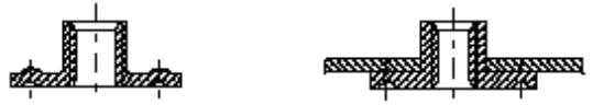
Steel Sheet Nuts
Category A
Category B
Styles
Square nut (MBN 73C or DIN 928)
Hexagonal Nut (MBN 73B or DIN 929)
Round Weld Nut (MBN 10369)
Style A Style B
Hexagonal Nut with Flange (MBN 10176)
Round Nut
Welding Stud
- Class A
- Class B
Example, MBN 75 MBN 10391
7 . Non-destructive testing
7.1 Description of the Procedure Sequence
All welds identified as defective through parameter monitoring (such as color marking) must be repaired.
Additional test samples must be separated from the specified random test pieces being produced. Relevant process documents should be consulted when inspecting weld studs and nuts.
The inspection department needs to record the inspection process in detail, such as identifying defects in the test piece.
7.2 Visual Inspection
7.2.1 Inspection Process
Visual inspections must meet assessment standards. They must be conducted by trained inspectors, under adequate distance and lighting conditions.
7.2.2 Inspection Records
Visual inspections should be recorded on a checklist.
Confirmed defects, such as weld points tending to the edge, must be corrected immediately in the production system or welding equipment.
7.2.3 Assessment Standards
Inspection of welded nuts must comply with the standards in the table below.
| Serial number | Evaluation criteria: | Example | |
| 1 | Missed pin/nut welds |
|
|
| two | Stud/nut damage or contamination (including weld spatter and thread damage) |
|

|
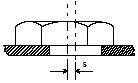
| 3 | The gap is inappropriate h > 0.1 m |
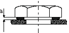
|
|
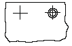
| 4 | Deviation from the center position The nuts must not obstruct the installation of the screws. |
|
|
| Reference values: For nuts with M ≤ 5, S must be ≤ 1mm. For nuts with M ≥ 6, S must be ≤ 2mm. For round arched nuts, S must be < 0.8 mm. |
|||
7.3 Torque Test
7.3.1 Welded nuts
Before performing torque tests on welded nuts, an external inspection is required. Inspection standards are as per 7.2.3. Torque testing must be performed using a torque wrench that is within the appropriate test range.
During the testing process, a torque is applied to the nut. If the weld seam is sheared or cracked before reaching the minimum torque, the strength will be considered insufficient.
Test standards are detailed in 7.3.3.
| Torque Measurement | |
| M4 | 6Nm |
| M5 | 8Nm |
| M6 | 14Nm |
| M8 | 32 Nm |
| M10 | 70 Nm |
| M12 | 100 Nm |
Note: Torque inspection should be carried out on square and hexagonal nuts, while the thickness of the steel plate does not need to be considered for round and arc-shaped nuts.
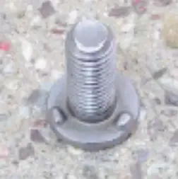
7.3.2 Welding Studs
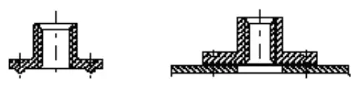
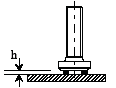
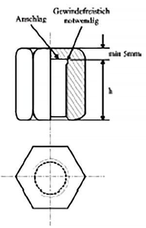
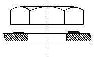
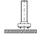
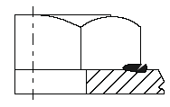
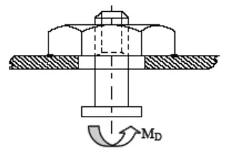
During the torque inspection process, first tighten the two nuts on the welding stud (as shown in Figure 1), and then apply a predetermined Mtest inspection torque with a suitable torque wrench, thereby subjecting the nut to a load of twist (as shown in Figure 2).
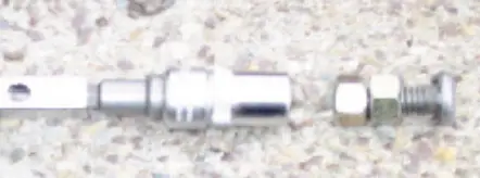
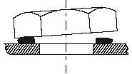
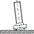
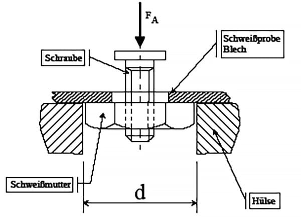
Afterwards, remove the two nuts. It is plausible to use an appropriate nut (as shown in Figure 3). Install the nut completely and then check the torque.
7.3.3 Assessment Criteria
After torque inspection, the installation of bolts and nuts should be evaluated based on the descriptions provided in the table below.
| Serial number | Rating criteria | Example | |
| 1 | Screws or nuts must not be loose |
|
|
| two | Weld seams must not be separated |
|
|
| 3 | Weld seams must not be damaged (cracked) |
|
7.3.4 Torque Test of Circular Nuts MBN 10369 and MBN 10390 (Arc Nuts)
Before performing torque tests on circular nuts, visual inspections must first be carried out as specified in section 7.2.3. Start by screwing a bolt into the circular nut using a torque wrench with an appropriate torque range.
During the test, the nut is subjected to bolt torque. If a crack appears in the seam before reaching the minimum torque, its strength will be considered insufficient. The test pattern is in section 7.3.3.
- Minimum torque for M5 circular nut: 8Nm
- Minimum torque for M6 circular nut: 14Nm
- Minimum torque for M8 circular nut: 32Nm
- Minimum torque for M10 circular nut: 70Nm
- Minimum torque for M20 circular nut: 100Nm
7.3.5 Torque Test of Ground Nuts
Before performing torque tests, visual inspections need to be carried out first, as indicated in section 7.2.3. Start by screwing a screw into the ground nut using a torque wrench with an appropriate torque range.
During the test, the nut is subjected to bolt torque. If a crack appears in the seam before reaching the minimum torque, the strength is considered insufficient. The test pattern is in section 7.3.3.
- Torque for M6 ground nut: 14Nm
- Torque for M8 ground nut: 27Nm
7.3.6 Torque Testing of Inaccessible Nuts
For nuts installed in cavities that do not require regular testing, they can be tested using grub screws. Screw the grub screw into the nut, and then use a torque wrench with an appropriate torque range to test the nut torque.
If a crack appears in the nut before reaching the minimum torque, the strength is considered insufficient. The test pattern is in section 7.3.3.
| Torque Measurement | |
| M4 | 4Nm |
| M5 | 5Nm |
| M6 | 8Nm |
| M8 | 20 Nm |
| M10 | 50 Nm |
| M12 | 80 Nm |
Note: Enhanced screws can be used if necessary.
8. Destructive Testing
Destructive testing is a special inspection carried out on the vehicle structure to improve quality and investigate quality problems.
8.1 Destructive Testing of Ground Nuts
Before inspecting the grounding nuts, a visual inspection, standardized in 7.3.3, must be carried out.
Use the appropriate tools to remove the welded steel plate from the ground nut.
Verify that 80% or more of the welding circumference is welded.
Note: 80% welding is sufficient for grounding.
8.2 Destructive Torque Test
Use a torque wrench with an appropriate torque range to determine how much torque you can unscrew the nut. The minimum weld separation torque is listed in Table 6.6.
8.2.1 Destructive torque test of round nuts MBN 10369 and MBN 10390 (arch nuts)
Destructive testing of round nuts is similar to non-destructive testing (see 7.2.3).
However, torque must be applied to the nut by the bolt until the weld fails. Same as torque wrench in Section 9.
8.2.2 Destructive Torque Test of Welding Bolts
Bolt destructive torque testing is similar to non-destructive testing (see 7.3.2).
However, torque must be applied to the nut by the bolt until the weld fails. Same as torque wrench in Section 9.
8.3 Compression Test
8.3.1 Test Sequence
The compressive strength of appropriate testing equipment must be capable of measuring the separated weld.
The force FA must be compared with the minimum force value in Table 8.4. Additionally, the fracture surface must be evaluated to determine whether a complete tack weld has formed.
8.3.2 Test Equipment
| Hexagonal nut | Square Nut | Diameter (mm) | Plate Thickness (mm) | Length (mm) |
| M3 | 10 | two | 40 | |
| M4 | M4 | 12 | ||
| M5 | M5 | 13 | ||
| M6 | M6 | 14 | ||
| M8 | 18 | |||
| M8 | 21 | |||
| M10 | 23 | |||
| M12 | M10 | 27 | ||
| M14 | M12 | 31 | ||
| M16 | M14 | 33 |
For components not listed in the table, such as screws or round nuts, inspection equipment should be similar to the above.
8.4 Strength Inspection List
The components mentioned in section six.
| Thread diameter | Plate Thickness | Compressive Strength |
| M4 | 0.75 1.0 1.5 |
>1.3kN |
| M5 | 0.75 1.0 1.5 |
>2.0kN |
| M6 | 1.0 1.5 2.5 |
>2.5kN |
| M8 | 1.0 2.0 3.0 |
>3.0kN |
| M10 | 1.25 2.0 3.0 |
>4.0kN |
| 07/16'' | 1.25 2.0 3.0 |
>5.0kN |
| M12 | 1.5 2.0 3.0 |
>6.0kN |
Excessive pressure that goes beyond the scope needs to be agreed with the relevant responsible departments.
8.5 Detachment Test Inspection
For welded steel plate nuts, a peeling method can be employed for inspection.
Using suitable tools, the nut is removed from the steel plate, such as a hammer, chisel or tension testing equipment.
Each weld spot needs to be checked to see whether the dimensions of the weld spot on the stripped steel plate are the same as before welding (for example, the minimum dimension of a 24mm diameter spot weld is 24mm; the minimum dimension of a pre-welded spot weld The 3x8mm solder spot is 3x8mm).
After inspection of all weld beads, if they meet the following conditions, they will be considered acceptable:
- 3 out of 4 solder points meet the requirements
- 2 out of 3 solder points meet the requirements
8.6 Inspection of Special Metal Sections
In special cases, a metal cross section can be used to inspect the fastening condition of screws and nuts.
Special inspection of metal cross sections requires operation by specially trained personnel.
Training guidelines must be issued by an authorized welding engineer or certified welding specialist.
9. Torque Test Table
As mentioned in Section 6, for parts.
| Destructive Testing | Non-destructive testing | ||
| Thread diameter | Plate Thickness | The torque setting in the welding system. | Torque monitoring during the part inspection process, which is related to the sheet thickness. |
| M4 | 0.7 1.25 1.5 |
13Nm 13Nm 16Nm |
6Nm 8Nm 8Nm |
| M5 | 0.7 1.25 1.5 |
20 Nm 29Nm 29Nm |
8Nm 10Nm 10Nm |
| M6 | 0.8 1.5 2.0 |
24 Nm 33 Nm 34 Nm |
14Nm 20 Nm 20 Nm |
| M8 | 1.0 2.0 3.0 |
58 Nm 61 Nm 60 Nm |
32 Nm 38 Nm 38 Nm |
| M107/16'' | 1.25 2.0 3.0 |
112 Nm 133 Nm 125 Nm |
70 Nm 90 Nm 90 Nm |
| M12 | >1.5 | 140 Nm | 100 Nm |
Note: The inspection standard in 6.2.3 is specific to thin steel sheets.
10. Inspection Document
Inspection of random samples must be recorded. The results of random inspections must be preserved for a period of time.
10.1 Corrective Measures for Defects
If defects are discovered during the inspection process, they must be corrected immediately. Furthermore, relevant systems must be inspected or patched.
All vehicles currently experiencing the same issues should be repaired. Defective rivet nuts must be removed, and to attach new screws or nuts, the plate surface must be kept clean and flat.
For individual cases where bolts and nuts cannot be replaced, suitable repair methods must be established through QPQ and EP/CSV.
11. Inspection Tools
The inspection department also needs to check the inspection tools.
The torque wrenches used must meet the following conditions:
- Torque working difference within 10% of inspection range
- Visible inspection results