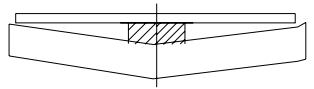
Geometric accuracy check
Blade edge gap uniformity
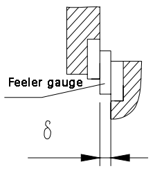
Inspection method and diagram
Adjust the shear angle to zero, move the tool holder down until the upper and lower blades coincide by 1-2 mm along the entire length, then turn off the main engine.
Measure the edge clearance 50mm away from the end face of the blade and then every 150mm along the blade. Calculate the error by taking the difference between the maximum and minimum clearances.
Tolerance: 0.05mm.
Parallelism between the lower blade and the stop
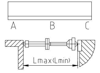
Inspection method and diagram
Adjust the stop to the maximum and minimum positions and measure the distance between the stop and the bottom blade in several locations, taking at least three measurements per meter. The error is calculated as the maximum value at any length of 1000 mm.
Note: The error value at point B can only be greater.
Tolerance (mm): 0.2/1000.
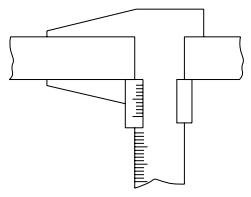
Rear retaining material positioning accuracy
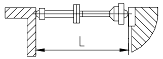
Inspection method and diagram
Three target positions must be set uniformly along the entire backstop travel, positioned from a fixed reference point based on linear or step cycle positive (or negative) feed.
The actual distance from the backstop should be measured using an inside micrometer and the error should be calculated as the maximum difference between the set position and the actual position.
Tolerance (mm): ±0.10
Repeatable positioning accuracy of the backstop
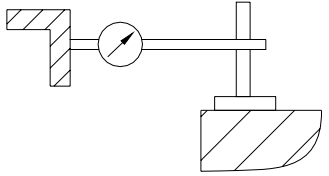
Inspection method and diagram
Set the back stop to a specific position, feed from the reference point to the target position, and fix the indicator on the mag meter base at the target position. The error is calculated as the difference between the maximum and minimum error values.
Tolerance (mm): 0.05
Work accuracy check
Test piece straightness
Inspection method and diagram
Place the test piece on the platform and position a 1000 mm long inspection ruler against its shear surface. Measure the distance between them using a feeler gauge and calculate the error as the maximum gap value.
Tolerance (mm): 0.2/1000
Test piece parallelism
Inspection method and diagram
Measure the width of the test piece in several locations (at least three per meter) using a caliper. The error should be calculated as the maximum reading difference at any length of 1000 mm.
Tolerance (mm): 0.2/1000
Note: Requirements for test pieces for work accuracy inspection:
- The length of the test piece (Lmax) must be the maximum shear width of the plate.
- The width (b) of the specimen must be 15 times the thickness of the shear plate, but not less than 80mm.
- The thickness of the specimen must be half the maximum shear thickness of the plate.
- The number of specimens must not be less than two.
- The end of the cut sheet must be equivalent to 10 times the thickness of the sheet without inspection. Local burrs and other defects on the cut section can be removed or pushed aside during measurement.